Magnetic electron microscope Stock Photos and Images
(57)See magnetic electron microscope stock video clipsQuick filters:
Magnetic electron microscope Stock Photos and Images
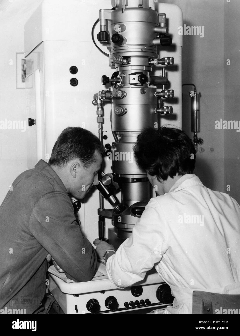 technology, general, science, working at electron microscope, 1950s, Additional-Rights-Clearance-Info-Not-Available Stock Photohttps://www.alamy.com/image-license-details/?v=1https://www.alamy.com/technology-general-science-working-at-electron-microscope-1950s-additional-rights-clearance-info-not-available-image240878563.html
RMRYTY1R–technology, general, science, working at electron microscope, 1950s, Additional-Rights-Clearance-Info-Not-Available
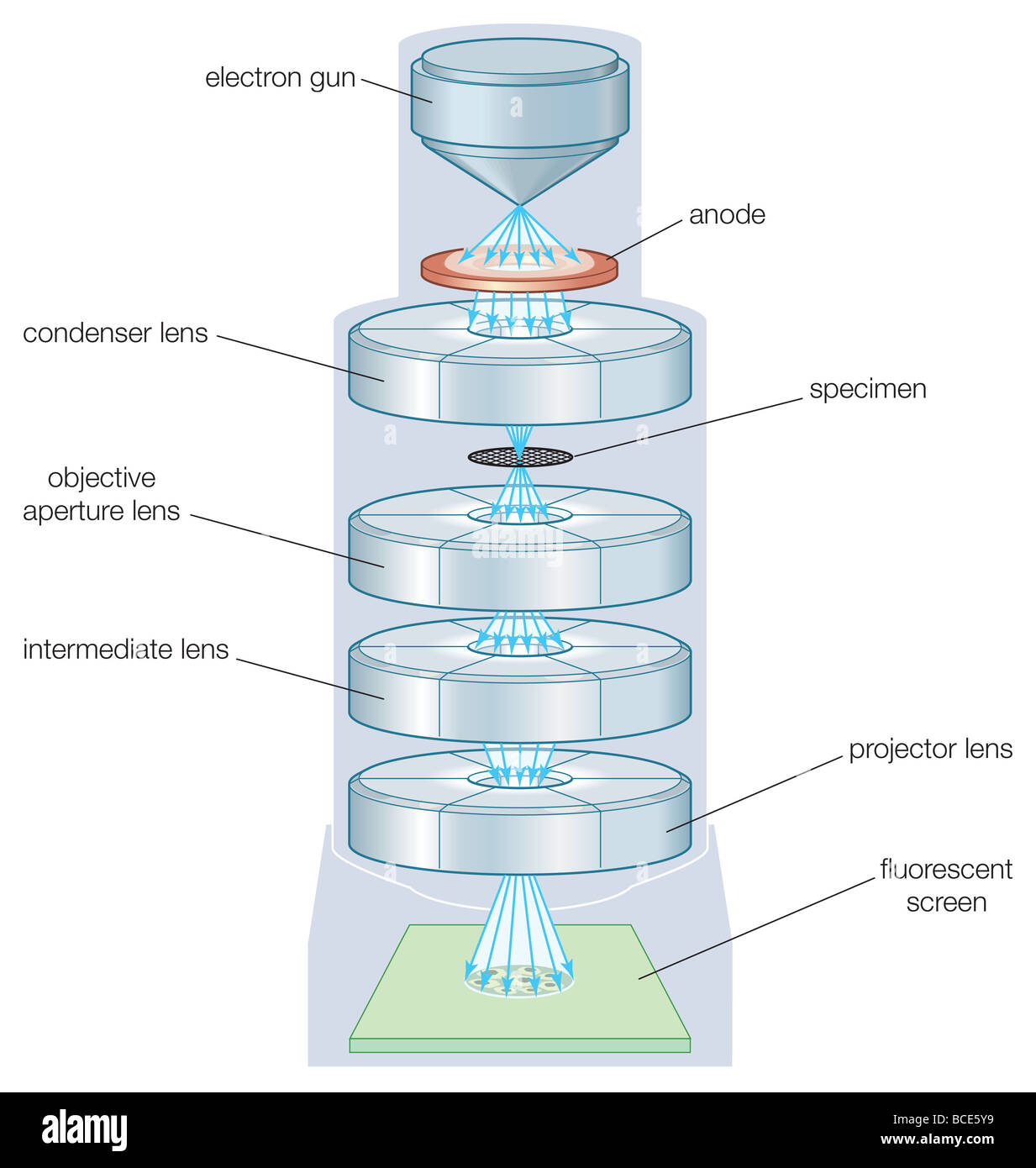 The components of a transmission electron microscope (TEM). Stock Photohttps://www.alamy.com/image-license-details/?v=1https://www.alamy.com/stock-photo-the-components-of-a-transmission-electron-microscope-tem-24898253.html
RMBCE5Y9–The components of a transmission electron microscope (TEM).
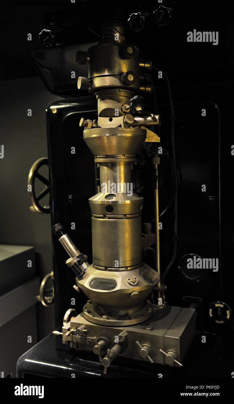 Electron microscope form the first series by Siemens, 1939. At Siemens B.v. Bories and E. Ruska developed the apparatus from 1937-1939. The microscope has three magnetic lenses, a resolution of about 3 nanometers and a magnification of about 3000. Deutches Museum. Munich. Germany. Stock Photohttps://www.alamy.com/image-license-details/?v=1https://www.alamy.com/electron-microscope-form-the-first-series-by-siemens-1939-at-siemens-bv-bories-and-e-ruska-developed-the-apparatus-from-1937-1939-the-microscope-has-three-magnetic-lenses-a-resolution-of-about-3-nanometers-and-a-magnification-of-about-3000-deutches-museum-munich-germany-image210234037.html
RMP60YJD–Electron microscope form the first series by Siemens, 1939. At Siemens B.v. Bories and E. Ruska developed the apparatus from 1937-1939. The microscope has three magnetic lenses, a resolution of about 3 nanometers and a magnification of about 3000. Deutches Museum. Munich. Germany.
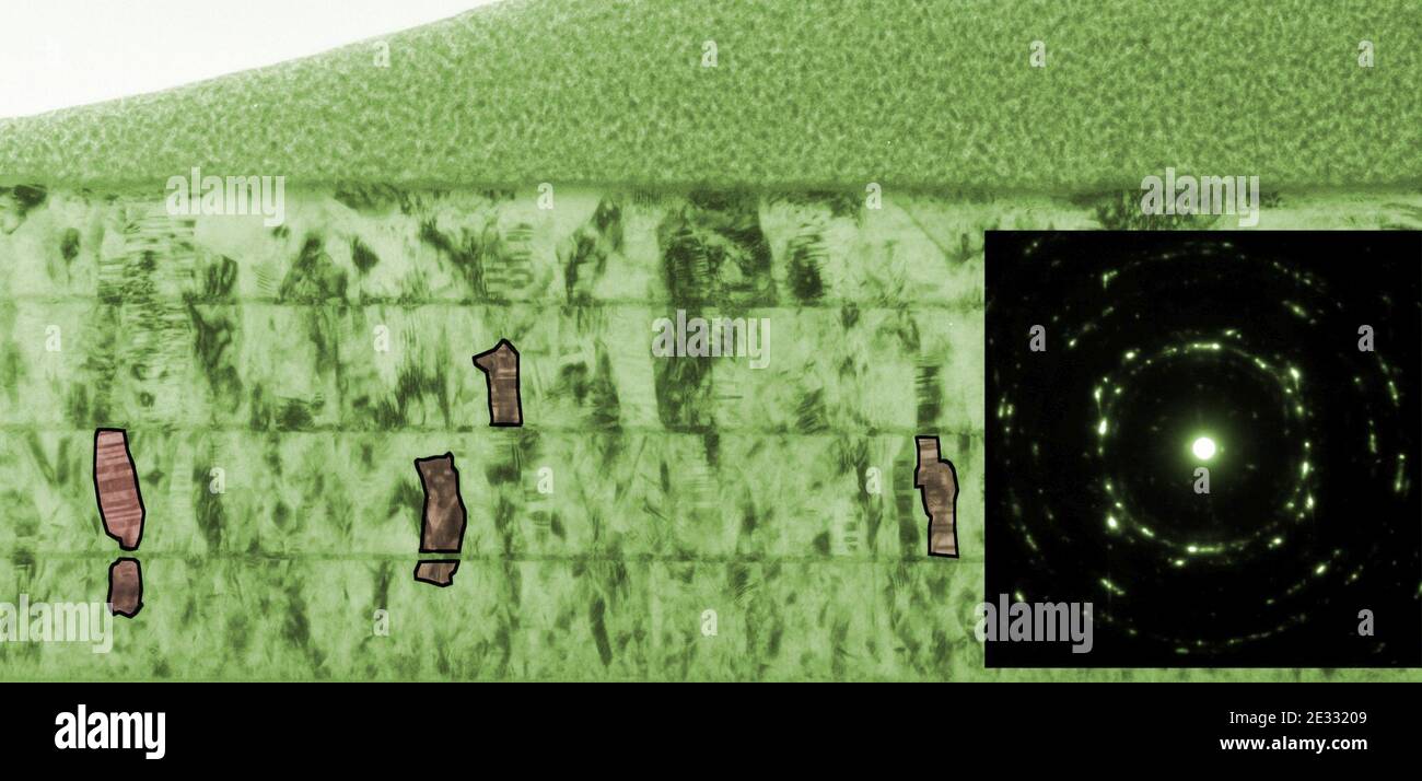 Magnetic fields; Transmission electron microscope (5884978267). Stock Photohttps://www.alamy.com/image-license-details/?v=1https://www.alamy.com/magnetic-fields-transmission-electron-microscope-5884978267-image397749865.html
RM2E33209–Magnetic fields; Transmission electron microscope (5884978267).
 . The electron microscope, its development, present performance and future possibilities. Electron microscopes. Supcniiicroscopes 33 of 1934. The whole coil is enclosed in the vacuum envelope. As outgasing of the insulation and of the long and narrow interstices. Fig. 11. E. Ruska's magnetic electron microscope of 1934 between the windings would be a very slow process, the whole coil is encased in metal. The gap in the iron casing is covered with non-magnetic material, such as brass. The pole pieces are interchangeable. In addition to these features, which recur in practically all modern micro Stock Photohttps://www.alamy.com/image-license-details/?v=1https://www.alamy.com/the-electron-microscope-its-development-present-performance-and-future-possibilities-electron-microscopes-supcniiicroscopes-33-of-1934-the-whole-coil-is-enclosed-in-the-vacuum-envelope-as-outgasing-of-the-insulation-and-of-the-long-and-narrow-interstices-fig-11-e-ruskas-magnetic-electron-microscope-of-1934-between-the-windings-would-be-a-very-slow-process-the-whole-coil-is-encased-in-metal-the-gap-in-the-iron-casing-is-covered-with-non-magnetic-material-such-as-brass-the-pole-pieces-are-interchangeable-in-addition-to-these-features-which-recur-in-practically-all-modern-micro-image231847502.html
RMRD5FRX–. The electron microscope, its development, present performance and future possibilities. Electron microscopes. Supcniiicroscopes 33 of 1934. The whole coil is enclosed in the vacuum envelope. As outgasing of the insulation and of the long and narrow interstices. Fig. 11. E. Ruska's magnetic electron microscope of 1934 between the windings would be a very slow process, the whole coil is encased in metal. The gap in the iron casing is covered with non-magnetic material, such as brass. The pole pieces are interchangeable. In addition to these features, which recur in practically all modern micro
RFFXAYKC–Science symbols icons doodle sketch
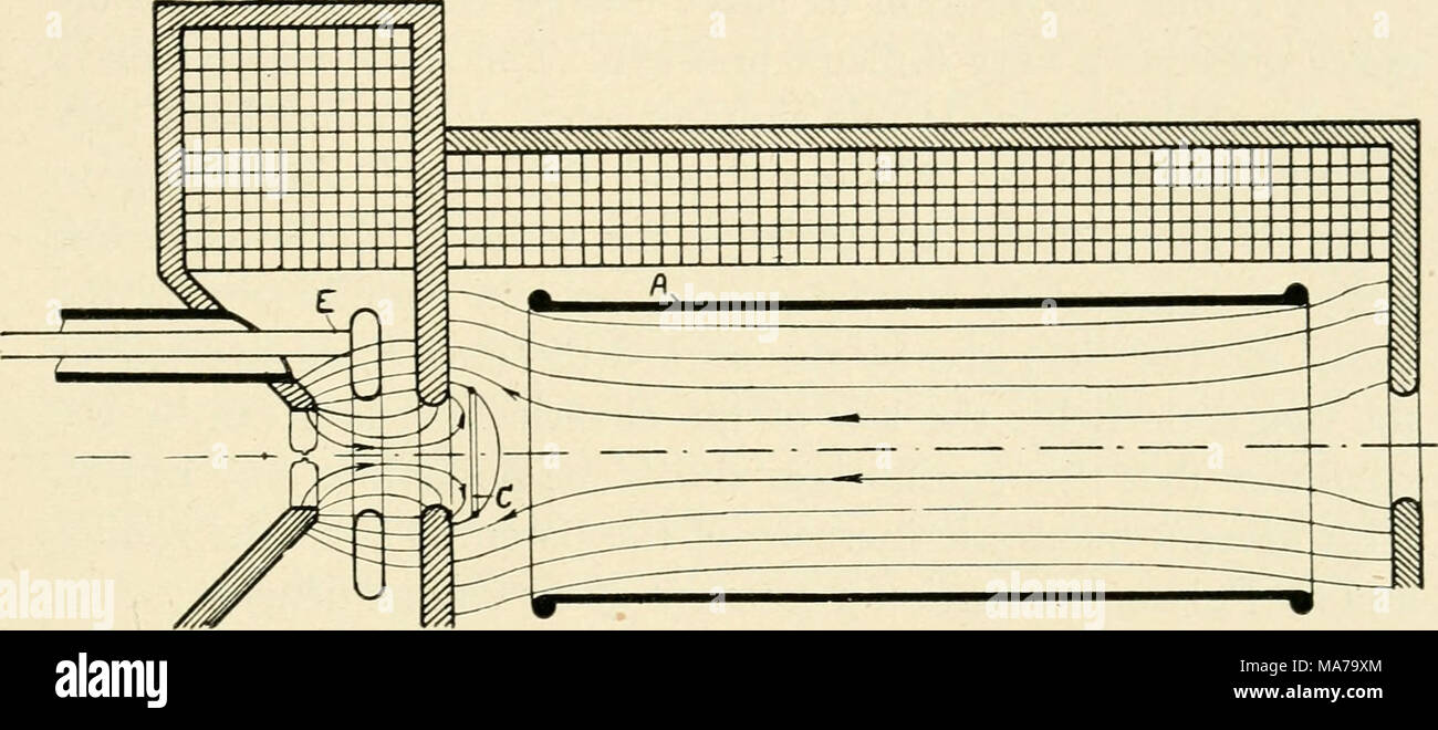 . The electron microscope, its development, present performance and future possibilities . 41a Magnetic Field Stock Photohttps://www.alamy.com/image-license-details/?v=1https://www.alamy.com/the-electron-microscope-its-development-present-performance-and-future-possibilities-41a-magnetic-field-image178411708.html
RMMA79XM–. The electron microscope, its development, present performance and future possibilities . 41a Magnetic Field
 Green Honeycomb Fluorescence Stock Photohttps://www.alamy.com/image-license-details/?v=1https://www.alamy.com/green-honeycomb-fluorescence-image600332139.html
RM2WTKDNF–Green Honeycomb Fluorescence
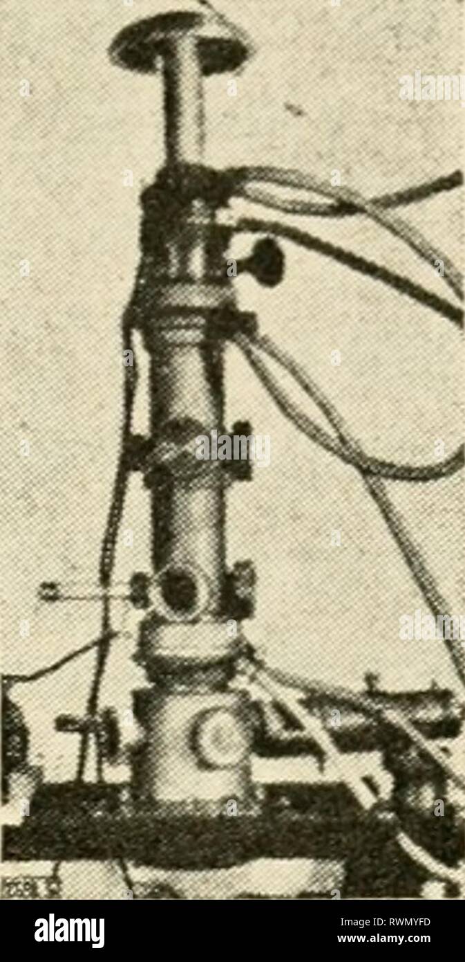 The electron microscope, its development, The electron microscope, its development, present performance and future possibilities electronmicrosco00gabo Year: 1948 Supcniiicroscopes 33 of 1934. The whole coil is enclosed in the vacuum envelope. As outgasing of the insulation and of the long and narrow interstices Fig. 11. E. Ruska's magnetic electron microscope of 1934 between the windings would be a very slow process, the whole coil is encased in metal. The gap in the iron casing is covered with non-magnetic material, such as brass. The pole pieces are interchangeable. In addition to these Stock Photohttps://www.alamy.com/image-license-details/?v=1https://www.alamy.com/the-electron-microscope-its-development-the-electron-microscope-its-development-present-performance-and-future-possibilities-electronmicrosco00gabo-year-1948-supcniiicroscopes-33-of-1934-the-whole-coil-is-enclosed-in-the-vacuum-envelope-as-outgasing-of-the-insulation-and-of-the-long-and-narrow-interstices-fig-11-e-ruskas-magnetic-electron-microscope-of-1934-between-the-windings-would-be-a-very-slow-process-the-whole-coil-is-encased-in-metal-the-gap-in-the-iron-casing-is-covered-with-non-magnetic-material-such-as-brass-the-pole-pieces-are-interchangeable-in-addition-to-these-image239561825.html
RMRWMYFD–The electron microscope, its development, The electron microscope, its development, present performance and future possibilities electronmicrosco00gabo Year: 1948 Supcniiicroscopes 33 of 1934. The whole coil is enclosed in the vacuum envelope. As outgasing of the insulation and of the long and narrow interstices Fig. 11. E. Ruska's magnetic electron microscope of 1934 between the windings would be a very slow process, the whole coil is encased in metal. The gap in the iron casing is covered with non-magnetic material, such as brass. The pole pieces are interchangeable. In addition to these
 Science symbols doodle sketch pictograms of relativity equation formula eureka moment and chemical reaction abstract vector illustration Stock Vectorhttps://www.alamy.com/image-license-details/?v=1https://www.alamy.com/science-symbols-doodle-sketch-pictograms-of-relativity-equation-formula-eureka-moment-and-chemical-reaction-abstract-vector-illustration-image398853219.html
RF2E4W99R–Science symbols doodle sketch pictograms of relativity equation formula eureka moment and chemical reaction abstract vector illustration
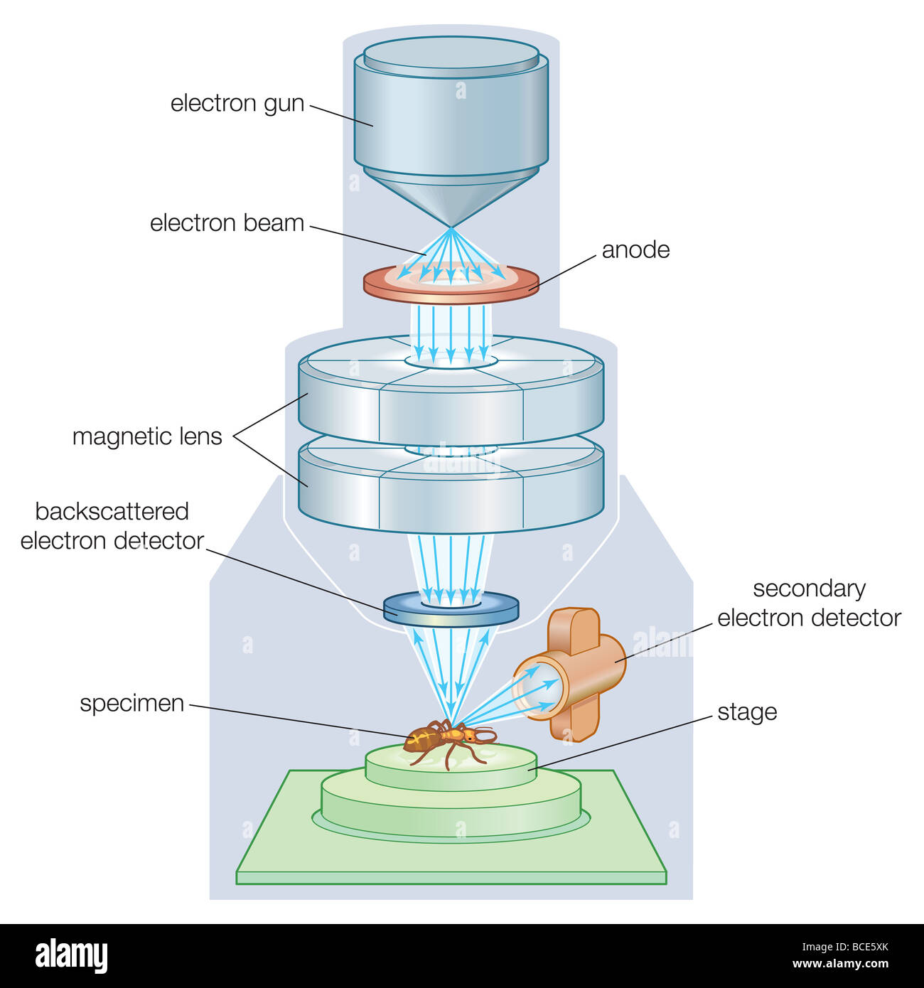 The components of a scanning electron microscope (SEM). Stock Photohttps://www.alamy.com/image-license-details/?v=1https://www.alamy.com/stock-photo-the-components-of-a-scanning-electron-microscope-sem-24898235.html
RMBCE5XK–The components of a scanning electron microscope (SEM).
 Scanning Transmission Electron Microscope TEM/STEM TitanTM G2 60-300 with imaging Cs-corrector is an advanced tool for structural characterization of materials at sub-Angstrom resolution Possessing a broad variety of complementary features, including X-FEG, monochromator, high-resolution Quantum GIF, EDX detector, electron bi-prism and Lorenz lens, this instrument allows to access structure, electronic and magnetic properties, as well as chemical compositions of nano-materials and nano-devices Atomic resolution imaging using TEM, High-Resolution Transmission Electron Microscopy Laboratory HR-T Stock Photohttps://www.alamy.com/image-license-details/?v=1https://www.alamy.com/scanning-transmission-electron-microscope-temstem-titantm-g2-60-300-with-imaging-cs-corrector-is-an-advanced-tool-for-structural-characterization-of-materials-at-sub-angstrom-resolution-possessing-a-broad-variety-of-complementary-features-including-x-feg-monochromator-high-resolution-quantum-gif-edx-detector-electron-bi-prism-and-lorenz-lens-this-instrument-allows-to-access-structure-electronic-and-magnetic-properties-as-well-as-chemical-compositions-of-nano-materials-and-nano-devices-atomic-resolution-imaging-using-tem-high-resolution-transmission-electron-microscopy-laboratory-hr-t-image602332797.html
RM2WYXHHH–Scanning Transmission Electron Microscope TEM/STEM TitanTM G2 60-300 with imaging Cs-corrector is an advanced tool for structural characterization of materials at sub-Angstrom resolution Possessing a broad variety of complementary features, including X-FEG, monochromator, high-resolution Quantum GIF, EDX detector, electron bi-prism and Lorenz lens, this instrument allows to access structure, electronic and magnetic properties, as well as chemical compositions of nano-materials and nano-devices Atomic resolution imaging using TEM, High-Resolution Transmission Electron Microscopy Laboratory HR-T
 . The electron microscope, its development, present performance and future possibilities. Electron microscopes. 41a Magnetic Field. 41b Electrostatic Field Corrected Objective Fig. 41 At the ends, where the magnetic field goes to zero, limitation is obtained by negative potentials, which means that the poten-. Please note that these images are extracted from scanned page images that may have been digitally enhanced for readability - coloration and appearance of these illustrations may not perfectly resemble the original work.. Gabor, Dennis, 1900-. Brooklyn, Chemical Pub. Co. Stock Photohttps://www.alamy.com/image-license-details/?v=1https://www.alamy.com/the-electron-microscope-its-development-present-performance-and-future-possibilities-electron-microscopes-41a-magnetic-field-41b-electrostatic-field-corrected-objective-fig-41-at-the-ends-where-the-magnetic-field-goes-to-zero-limitation-is-obtained-by-negative-potentials-which-means-that-the-poten-please-note-that-these-images-are-extracted-from-scanned-page-images-that-may-have-been-digitally-enhanced-for-readability-coloration-and-appearance-of-these-illustrations-may-not-perfectly-resemble-the-original-work-gabor-dennis-1900-brooklyn-chemical-pub-co-image231864673.html
RMRD69N5–. The electron microscope, its development, present performance and future possibilities. Electron microscopes. 41a Magnetic Field. 41b Electrostatic Field Corrected Objective Fig. 41 At the ends, where the magnetic field goes to zero, limitation is obtained by negative potentials, which means that the poten-. Please note that these images are extracted from scanned page images that may have been digitally enhanced for readability - coloration and appearance of these illustrations may not perfectly resemble the original work.. Gabor, Dennis, 1900-. Brooklyn, Chemical Pub. Co.
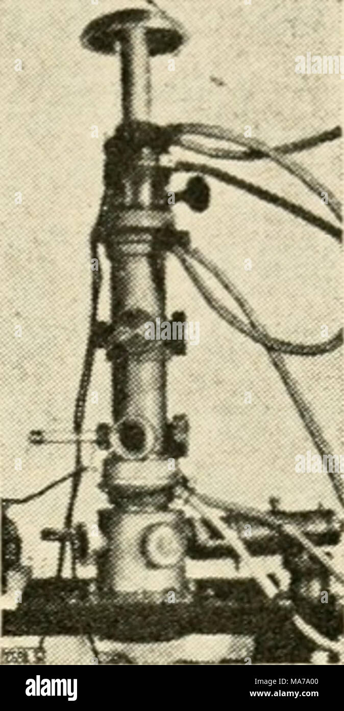 . The electron microscope, its development, present performance and future possibilities . Fig. 11. E. Ruska's magnetic electron microscope of 1934 between the windings would be a very slow process, the whole coil is encased in metal. The gap in the iron casing is covered with non-magnetic material, such as brass. The pole pieces are interchangeable. In addition to these features, which recur in practically all modern microscopes, Ruska's design provides water cooling, a complication which was later found unnecessary. Comparing the optical systems of an electron microscope and an optical micro Stock Photohttps://www.alamy.com/image-license-details/?v=1https://www.alamy.com/the-electron-microscope-its-development-present-performance-and-future-possibilities-fig-11-e-ruskas-magnetic-electron-microscope-of-1934-between-the-windings-would-be-a-very-slow-process-the-whole-coil-is-encased-in-metal-the-gap-in-the-iron-casing-is-covered-with-non-magnetic-material-such-as-brass-the-pole-pieces-are-interchangeable-in-addition-to-these-features-which-recur-in-practically-all-modern-microscopes-ruskas-design-provides-water-cooling-a-complication-which-was-later-found-unnecessary-comparing-the-optical-systems-of-an-electron-microscope-and-an-optical-micro-image178411744.html
RMMA7A00–. The electron microscope, its development, present performance and future possibilities . Fig. 11. E. Ruska's magnetic electron microscope of 1934 between the windings would be a very slow process, the whole coil is encased in metal. The gap in the iron casing is covered with non-magnetic material, such as brass. The pole pieces are interchangeable. In addition to these features, which recur in practically all modern microscopes, Ruska's design provides water cooling, a complication which was later found unnecessary. Comparing the optical systems of an electron microscope and an optical micro
 The electron microscope, its development, present performance and future possibilities electronmicrosco00gabo Year: 1948 Supcniiicroscopes 33 of 1934. The whole coil is enclosed in the vacuum envelope. As outgasing of the insulation and of the long and narrow interstices Fig. 11. E. Ruska's magnetic electron microscope of 1934 between the windings would be a very slow process, the whole coil is encased in metal. The gap in the iron casing is covered with non-magnetic material, such as brass. The pole pieces are interchangeable. In addition to these features, which recur in practically all Stock Photohttps://www.alamy.com/image-license-details/?v=1https://www.alamy.com/the-electron-microscope-its-development-present-performance-and-future-possibilities-electronmicrosco00gabo-year-1948-supcniiicroscopes-33-of-1934-the-whole-coil-is-enclosed-in-the-vacuum-envelope-as-outgasing-of-the-insulation-and-of-the-long-and-narrow-interstices-fig-11-e-ruskas-magnetic-electron-microscope-of-1934-between-the-windings-would-be-a-very-slow-process-the-whole-coil-is-encased-in-metal-the-gap-in-the-iron-casing-is-covered-with-non-magnetic-material-such-as-brass-the-pole-pieces-are-interchangeable-in-addition-to-these-features-which-recur-in-practically-all-image240686923.html
RMRYG6HF–The electron microscope, its development, present performance and future possibilities electronmicrosco00gabo Year: 1948 Supcniiicroscopes 33 of 1934. The whole coil is enclosed in the vacuum envelope. As outgasing of the insulation and of the long and narrow interstices Fig. 11. E. Ruska's magnetic electron microscope of 1934 between the windings would be a very slow process, the whole coil is encased in metal. The gap in the iron casing is covered with non-magnetic material, such as brass. The pole pieces are interchangeable. In addition to these features, which recur in practically all
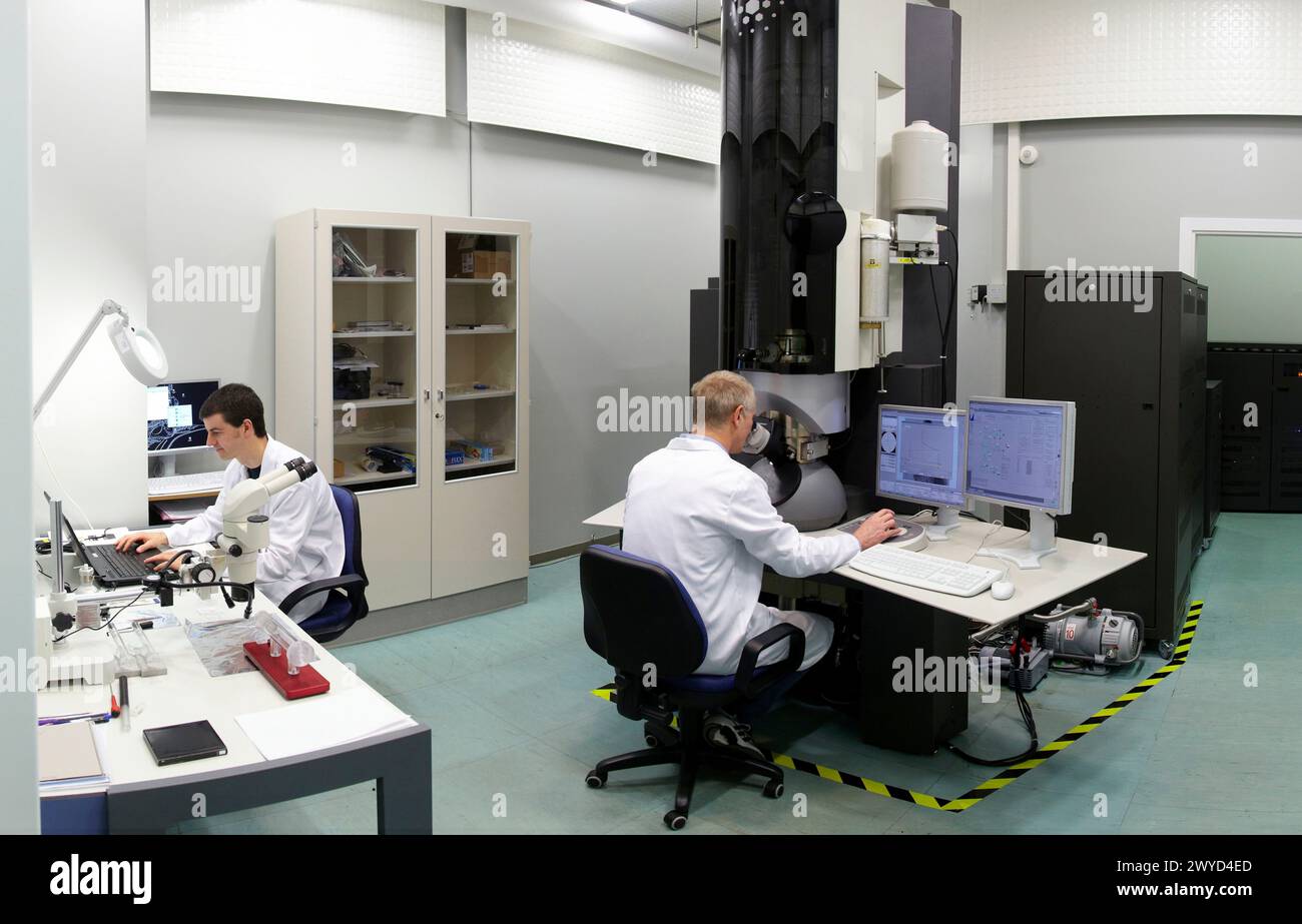 Scanning Transmission Electron Microscope TEM/STEM TitanTM G2 60-300 with imaging Cs-corrector is an advanced tool for structural characterization of materials at sub-Angstrom resolution Possessing a broad variety of complementary features, including X-FEG, monochromator, high-resolution Quantum GIF, EDX detector, electron bi-prism and Lorenz lens, this instrument allows to access structure, electronic and magnetic properties, as well as chemical compositions of nano-materials and nano-devices Atomic resolution imaging using TEM, High-Resolution Transmission Electron Microscopy Laboratory HR-T Stock Photohttps://www.alamy.com/image-license-details/?v=1https://www.alamy.com/scanning-transmission-electron-microscope-temstem-titantm-g2-60-300-with-imaging-cs-corrector-is-an-advanced-tool-for-structural-characterization-of-materials-at-sub-angstrom-resolution-possessing-a-broad-variety-of-complementary-features-including-x-feg-monochromator-high-resolution-quantum-gif-edx-detector-electron-bi-prism-and-lorenz-lens-this-instrument-allows-to-access-structure-electronic-and-magnetic-properties-as-well-as-chemical-compositions-of-nano-materials-and-nano-devices-atomic-resolution-imaging-using-tem-high-resolution-transmission-electron-microscopy-laboratory-hr-t-image602037141.html
RM2WYD4ED–Scanning Transmission Electron Microscope TEM/STEM TitanTM G2 60-300 with imaging Cs-corrector is an advanced tool for structural characterization of materials at sub-Angstrom resolution Possessing a broad variety of complementary features, including X-FEG, monochromator, high-resolution Quantum GIF, EDX detector, electron bi-prism and Lorenz lens, this instrument allows to access structure, electronic and magnetic properties, as well as chemical compositions of nano-materials and nano-devices Atomic resolution imaging using TEM, High-Resolution Transmission Electron Microscopy Laboratory HR-T
 . The electron microscope, its development, present performance and future possibilities. Electron microscopes. 116 Tlie Electron Microscope stant is determined by the ratio beween electron injection and removal. If the removal is negligible, electrons will accumulate in the accessible space until they have depressed the potential at the inner radius to the level of the cathode potential. The inner radius itself moves outward during this accumulation, until it reaches the magnetic field line passing through the cathode. From this moment on, no further electrons can leave the cathode; the cloud Stock Photohttps://www.alamy.com/image-license-details/?v=1https://www.alamy.com/the-electron-microscope-its-development-present-performance-and-future-possibilities-electron-microscopes-116-tlie-electron-microscope-stant-is-determined-by-the-ratio-beween-electron-injection-and-removal-if-the-removal-is-negligible-electrons-will-accumulate-in-the-accessible-space-until-they-have-depressed-the-potential-at-the-inner-radius-to-the-level-of-the-cathode-potential-the-inner-radius-itself-moves-outward-during-this-accumulation-until-it-reaches-the-magnetic-field-line-passing-through-the-cathode-from-this-moment-on-no-further-electrons-can-leave-the-cathode-the-cloud-image231864672.html
RMRD69N4–. The electron microscope, its development, present performance and future possibilities. Electron microscopes. 116 Tlie Electron Microscope stant is determined by the ratio beween electron injection and removal. If the removal is negligible, electrons will accumulate in the accessible space until they have depressed the potential at the inner radius to the level of the cathode potential. The inner radius itself moves outward during this accumulation, until it reaches the magnetic field line passing through the cathode. From this moment on, no further electrons can leave the cathode; the cloud
 . The electron microscope, its development, present performance and future possibilities . 41b Electrostatic Field Corrected Objective Fig. 41 At the ends, where the magnetic field goes to zero, limitation is obtained by negative potentials, which means that the poten- Stock Photohttps://www.alamy.com/image-license-details/?v=1https://www.alamy.com/the-electron-microscope-its-development-present-performance-and-future-possibilities-41b-electrostatic-field-corrected-objective-fig-41-at-the-ends-where-the-magnetic-field-goes-to-zero-limitation-is-obtained-by-negative-potentials-which-means-that-the-poten-image178411707.html
RMMA79XK–. The electron microscope, its development, present performance and future possibilities . 41b Electrostatic Field Corrected Objective Fig. 41 At the ends, where the magnetic field goes to zero, limitation is obtained by negative potentials, which means that the poten-
 The electron microscope, its development, The electron microscope, its development, present performance and future possibilities . electronmicrosco00gabo Year: 1948 41a Magnetic Field 41b Electrostatic Field Corrected Objective Fig. 41 At the ends, where the magnetic field goes to zero, limitation is obtained by negative potentials, which means that the poten- Stock Photohttps://www.alamy.com/image-license-details/?v=1https://www.alamy.com/the-electron-microscope-its-development-the-electron-microscope-its-development-present-performance-and-future-possibilities-electronmicrosco00gabo-year-1948-41a-magnetic-field-41b-electrostatic-field-corrected-objective-fig-41-at-the-ends-where-the-magnetic-field-goes-to-zero-limitation-is-obtained-by-negative-potentials-which-means-that-the-poten-image240836546.html
RMRYR1D6–The electron microscope, its development, The electron microscope, its development, present performance and future possibilities . electronmicrosco00gabo Year: 1948 41a Magnetic Field 41b Electrostatic Field Corrected Objective Fig. 41 At the ends, where the magnetic field goes to zero, limitation is obtained by negative potentials, which means that the poten-
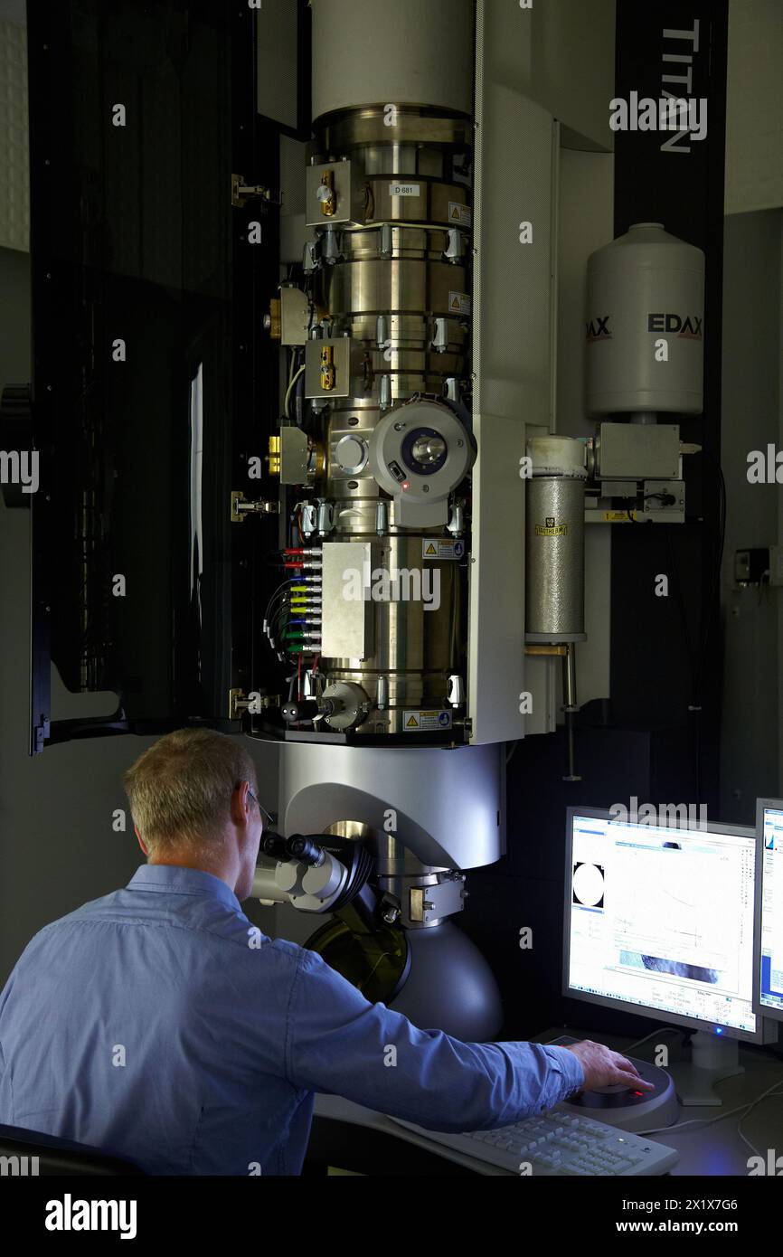 Scanning Transmission Electron Microscope TEM/STEM TitanTM G2 60-300 with imaging Cs-corrector is an advanced tool for structural characterization of materials at sub-Angstrom resolution Possessing a broad variety of complementary features, including X-FEG, monochromator, high-resolution Quantum GIF, EDX detector, electron bi-prism and Lorenz lens, this instrument allows to access structure, electronic and magnetic properties, as well as chemical compositions of nano-materials and nano-devices Atomic resolution imaging using TEM, High-Resolution Transmission Electron Microscopy Laboratory HR-T Stock Photohttps://www.alamy.com/image-license-details/?v=1https://www.alamy.com/scanning-transmission-electron-microscope-temstem-titantm-g2-60-300-with-imaging-cs-corrector-is-an-advanced-tool-for-structural-characterization-of-materials-at-sub-angstrom-resolution-possessing-a-broad-variety-of-complementary-features-including-x-feg-monochromator-high-resolution-quantum-gif-edx-detector-electron-bi-prism-and-lorenz-lens-this-instrument-allows-to-access-structure-electronic-and-magnetic-properties-as-well-as-chemical-compositions-of-nano-materials-and-nano-devices-atomic-resolution-imaging-using-tem-high-resolution-transmission-electron-microscopy-laboratory-hr-t-image603554230.html
RM2X1X7G6–Scanning Transmission Electron Microscope TEM/STEM TitanTM G2 60-300 with imaging Cs-corrector is an advanced tool for structural characterization of materials at sub-Angstrom resolution Possessing a broad variety of complementary features, including X-FEG, monochromator, high-resolution Quantum GIF, EDX detector, electron bi-prism and Lorenz lens, this instrument allows to access structure, electronic and magnetic properties, as well as chemical compositions of nano-materials and nano-devices Atomic resolution imaging using TEM, High-Resolution Transmission Electron Microscopy Laboratory HR-T
 . The electron microscope, its development, present performance and future possibilities. Electron microscopes. 8 The Electron Microscope That is, the angular momentum changes proportionally to the magnetic flux which passes between the tzvo coaxial circles drawn through the initial and final positions respectively. This result can be put into an even simpler form if we intro- duce the vectorpotential A, from which the vector H of the magnetic field intensity can be derived by the operation H = curl A. In the case of axially symmetrical fields the vector A has always tangential direction, ther Stock Photohttps://www.alamy.com/image-license-details/?v=1https://www.alamy.com/the-electron-microscope-its-development-present-performance-and-future-possibilities-electron-microscopes-8-the-electron-microscope-that-is-the-angular-momentum-changes-proportionally-to-the-magnetic-flux-which-passes-between-the-tzvo-coaxial-circles-drawn-through-the-initial-and-final-positions-respectively-this-result-can-be-put-into-an-even-simpler-form-if-we-intro-duce-the-vectorpotential-a-from-which-the-vector-h-of-the-magnetic-field-intensity-can-be-derived-by-the-operation-h-=-curl-a-in-the-case-of-axially-symmetrical-fields-the-vector-a-has-always-tangential-direction-ther-image231847520.html
RMRD5FTG–. The electron microscope, its development, present performance and future possibilities. Electron microscopes. 8 The Electron Microscope That is, the angular momentum changes proportionally to the magnetic flux which passes between the tzvo coaxial circles drawn through the initial and final positions respectively. This result can be put into an even simpler form if we intro- duce the vectorpotential A, from which the vector H of the magnetic field intensity can be derived by the operation H = curl A. In the case of axially symmetrical fields the vector A has always tangential direction, ther
 . The electron microscope, its development, present performance and future possibilities . Fig. 17. Type B floor model and experimental desk model of R.C.A. magnetic microscopes Figure 18 is a schematic section of the microscope. From top to bottom, it contains the discharge tube, a flexible joint with a double set of adjusting screws, the condenser lens, a second flexible joint, the object chamber, the objective lens, a third flexible joint, connecting the objective with the first throw, the Stock Photohttps://www.alamy.com/image-license-details/?v=1https://www.alamy.com/the-electron-microscope-its-development-present-performance-and-future-possibilities-fig-17-type-b-floor-model-and-experimental-desk-model-of-rca-magnetic-microscopes-figure-18-is-a-schematic-section-of-the-microscope-from-top-to-bottom-it-contains-the-discharge-tube-a-flexible-joint-with-a-double-set-of-adjusting-screws-the-condenser-lens-a-second-flexible-joint-the-object-chamber-the-objective-lens-a-third-flexible-joint-connecting-the-objective-with-the-first-throw-the-image178411743.html
RMMA79YY–. The electron microscope, its development, present performance and future possibilities . Fig. 17. Type B floor model and experimental desk model of R.C.A. magnetic microscopes Figure 18 is a schematic section of the microscope. From top to bottom, it contains the discharge tube, a flexible joint with a double set of adjusting screws, the condenser lens, a second flexible joint, the object chamber, the objective lens, a third flexible joint, connecting the objective with the first throw, the
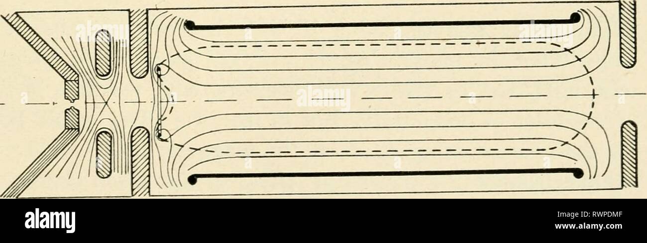 The electron microscope, its development, The electron microscope, its development, present performance and future possibilities electronmicrosco00gabo Year: 1948 41a Magnetic Field 41b Electrostatic Field Corrected Objective Fig. 41 At the ends, where the magnetic field goes to zero, limitation is obtained by negative potentials, which means that the poten- Stock Photohttps://www.alamy.com/image-license-details/?v=1https://www.alamy.com/the-electron-microscope-its-development-the-electron-microscope-its-development-present-performance-and-future-possibilities-electronmicrosco00gabo-year-1948-41a-magnetic-field-41b-electrostatic-field-corrected-objective-fig-41-at-the-ends-where-the-magnetic-field-goes-to-zero-limitation-is-obtained-by-negative-potentials-which-means-that-the-poten-image239594895.html
RMRWPDMF–The electron microscope, its development, The electron microscope, its development, present performance and future possibilities electronmicrosco00gabo Year: 1948 41a Magnetic Field 41b Electrostatic Field Corrected Objective Fig. 41 At the ends, where the magnetic field goes to zero, limitation is obtained by negative potentials, which means that the poten-
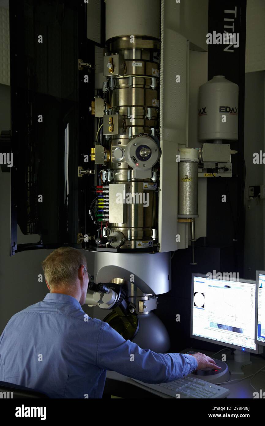 Scanning Transmission Electron Microscope TEM/STEM TitanTM G2 60-300 with imaging Cs-corrector is an advanced tool for structural characterization of materials at sub-Angstrom resolution Possessing a broad variety of complementary features, including X-FEG, monochromator, high-resolution Quantum GIF, EDX detector, electron bi-prism and Lorenz lens, this instrument allows to access structure, electronic and magnetic properties, as well as chemical compositions of nano-materials and nano-devices Atomic resolution imaging using TEM, High-Resolution Transmission Electron Microscopy Laboratory HR-T Stock Photohttps://www.alamy.com/image-license-details/?v=1https://www.alamy.com/scanning-transmission-electron-microscope-temstem-titantm-g2-60-300-with-imaging-cs-corrector-is-an-advanced-tool-for-structural-characterization-of-materials-at-sub-angstrom-resolution-possessing-a-broad-variety-of-complementary-features-including-x-feg-monochromator-high-resolution-quantum-gif-edx-detector-electron-bi-prism-and-lorenz-lens-this-instrument-allows-to-access-structure-electronic-and-magnetic-properties-as-well-as-chemical-compositions-of-nano-materials-and-nano-devices-atomic-resolution-imaging-using-tem-high-resolution-transmission-electron-microscopy-laboratory-hr-t-image624979954.html
RM2Y8P88J–Scanning Transmission Electron Microscope TEM/STEM TitanTM G2 60-300 with imaging Cs-corrector is an advanced tool for structural characterization of materials at sub-Angstrom resolution Possessing a broad variety of complementary features, including X-FEG, monochromator, high-resolution Quantum GIF, EDX detector, electron bi-prism and Lorenz lens, this instrument allows to access structure, electronic and magnetic properties, as well as chemical compositions of nano-materials and nano-devices Atomic resolution imaging using TEM, High-Resolution Transmission Electron Microscopy Laboratory HR-T
 . The electron microscope, its development, present performance and future possibilities. Electron microscopes. Geometrical Electron Optics 11 transversal spherical aberration. In fact, the bundle has its smallest cross section not at p but at m, which is called the disc of minimum confusion. Its radius is one quarter of the spherical aberration. When an electron lens is focused, it is always m, not p, which is made to coincide with the screen or plate. Scherzer ^ has proved the important theorem that in electron lenses, whether electrostatic, magnetic, or combined, the spherical. Fig. 4. Sphe Stock Photohttps://www.alamy.com/image-license-details/?v=1https://www.alamy.com/the-electron-microscope-its-development-present-performance-and-future-possibilities-electron-microscopes-geometrical-electron-optics-11-transversal-spherical-aberration-in-fact-the-bundle-has-its-smallest-cross-section-not-at-p-but-at-m-which-is-called-the-disc-of-minimum-confusion-its-radius-is-one-quarter-of-the-spherical-aberration-when-an-electron-lens-is-focused-it-is-always-m-not-p-which-is-made-to-coincide-with-the-screen-or-plate-scherzer-has-proved-the-important-theorem-that-in-electron-lenses-whether-electrostatic-magnetic-or-combined-the-spherical-fig-4-sphe-image231847516.html
RMRD5FTC–. The electron microscope, its development, present performance and future possibilities. Electron microscopes. Geometrical Electron Optics 11 transversal spherical aberration. In fact, the bundle has its smallest cross section not at p but at m, which is called the disc of minimum confusion. Its radius is one quarter of the spherical aberration. When an electron lens is focused, it is always m, not p, which is made to coincide with the screen or plate. Scherzer ^ has proved the important theorem that in electron lenses, whether electrostatic, magnetic, or combined, the spherical. Fig. 4. Sphe
 . The electron microscope, its development, present performance and future possibilities . Fig. 40. Potential and trajectories in electrostatic lenses The space charge lens is essentially a cylindrical magnetron, but with the important difference that it contains no axial cathode. Its main parts are a long coil, which produces, at least in the middle part, a nearly homogeneous magnetic field, a tubular anode or sheath electrode *'A," and a cathode "C," which is a filament, bent to a coaxial circle. The currents are Stock Photohttps://www.alamy.com/image-license-details/?v=1https://www.alamy.com/the-electron-microscope-its-development-present-performance-and-future-possibilities-fig-40-potential-and-trajectories-in-electrostatic-lenses-the-space-charge-lens-is-essentially-a-cylindrical-magnetron-but-with-the-important-difference-that-it-contains-no-axial-cathode-its-main-parts-are-a-long-coil-which-produces-at-least-in-the-middle-part-a-nearly-homogeneous-magnetic-field-a-tubular-anode-or-sheath-electrode-aquot-and-a-cathode-quotcquot-which-is-a-filament-bent-to-a-coaxial-circle-the-currents-are-image178411713.html
RMMA79XW–. The electron microscope, its development, present performance and future possibilities . Fig. 40. Potential and trajectories in electrostatic lenses The space charge lens is essentially a cylindrical magnetron, but with the important difference that it contains no axial cathode. Its main parts are a long coil, which produces, at least in the middle part, a nearly homogeneous magnetic field, a tubular anode or sheath electrode *'A," and a cathode "C," which is a filament, bent to a coaxial circle. The currents are
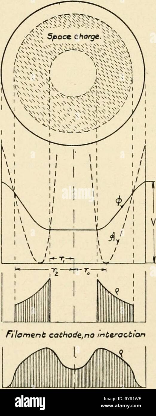 The electron microscope, its development, The electron microscope, its development, present performance and future possibilities . electronmicrosco00gabo Year: 1948 116 Tlie Electron Microscope stant is determined by the ratio beween electron injection and removal. If the removal is negligible, electrons will accumulate in the accessible space until they have depressed the potential at the inner radius to the level of the cathode potential. The inner radius itself moves outward during this accumulation, until it reaches the magnetic field line passing through the cathode. From this moment on, Stock Photohttps://www.alamy.com/image-license-details/?v=1https://www.alamy.com/the-electron-microscope-its-development-the-electron-microscope-its-development-present-performance-and-future-possibilities-electronmicrosco00gabo-year-1948-116-tlie-electron-microscope-stant-is-determined-by-the-ratio-beween-electron-injection-and-removal-if-the-removal-is-negligible-electrons-will-accumulate-in-the-accessible-space-until-they-have-depressed-the-potential-at-the-inner-radius-to-the-level-of-the-cathode-potential-the-inner-radius-itself-moves-outward-during-this-accumulation-until-it-reaches-the-magnetic-field-line-passing-through-the-cathode-from-this-moment-on-image240836890.html
RMRYR1WE–The electron microscope, its development, The electron microscope, its development, present performance and future possibilities . electronmicrosco00gabo Year: 1948 116 Tlie Electron Microscope stant is determined by the ratio beween electron injection and removal. If the removal is negligible, electrons will accumulate in the accessible space until they have depressed the potential at the inner radius to the level of the cathode potential. The inner radius itself moves outward during this accumulation, until it reaches the magnetic field line passing through the cathode. From this moment on,
 . The electron microscope, its development, present performance and future possibilities. Electron microscopes. Possibilities of Future Development 111 potential lens is connected with the cathode as usual, whereas the outer electrode, preferably earthed, is formed by.the pole pieces of the magnetic lens. The object is placed outside this lens, shielded from the strong electrostatic fields by an apertured diaphragm. The focal length of this first lens is supposed to be of the same order as in present-day microscopes, i.e., about 0.5 cm for 60 kev electrons.. Fig. 40. Potential and trajectories Stock Photohttps://www.alamy.com/image-license-details/?v=1https://www.alamy.com/the-electron-microscope-its-development-present-performance-and-future-possibilities-electron-microscopes-possibilities-of-future-development-111-potential-lens-is-connected-with-the-cathode-as-usual-whereas-the-outer-electrode-preferably-earthed-is-formed-bythe-pole-pieces-of-the-magnetic-lens-the-object-is-placed-outside-this-lens-shielded-from-the-strong-electrostatic-fields-by-an-apertured-diaphragm-the-focal-length-of-this-first-lens-is-supposed-to-be-of-the-same-order-as-in-present-day-microscopes-ie-about-05-cm-for-60-kev-electrons-fig-40-potential-and-trajectories-image231847427.html
RMRD5FN7–. The electron microscope, its development, present performance and future possibilities. Electron microscopes. Possibilities of Future Development 111 potential lens is connected with the cathode as usual, whereas the outer electrode, preferably earthed, is formed by.the pole pieces of the magnetic lens. The object is placed outside this lens, shielded from the strong electrostatic fields by an apertured diaphragm. The focal length of this first lens is supposed to be of the same order as in present-day microscopes, i.e., about 0.5 cm for 60 kev electrons.. Fig. 40. Potential and trajectories
 . The electron microscope, its development, present performance and future possibilities . / Lines A ^ consC (equivalent poteritial linesj Fig. 3. Magnetic lens This at once explains the lens effect of axially arranged coils. By its definition (3) the vectorpotential A is zero at the axis and increases approximately linearly with the radius r. This means that the equivalent potential decreases outside the axis and that the magnetic field has a repellent effect, i.e., it drives the elec- trons back, toward the axis. Therefore, a magnetic lens is always a condensing lens. An example is shown in Stock Photohttps://www.alamy.com/image-license-details/?v=1https://www.alamy.com/the-electron-microscope-its-development-present-performance-and-future-possibilities-lines-a-consc-equivalent-poteritial-linesj-fig-3-magnetic-lens-this-at-once-explains-the-lens-effect-of-axially-arranged-coils-by-its-definition-3-the-vectorpotential-a-is-zero-at-the-axis-and-increases-approximately-linearly-with-the-radius-r-this-means-that-the-equivalent-potential-decreases-outside-the-axis-and-that-the-magnetic-field-has-a-repellent-effect-ie-it-drives-the-elec-trons-back-toward-the-axis-therefore-a-magnetic-lens-is-always-a-condensing-lens-an-example-is-shown-in-image178411773.html
RMMA7A11–. The electron microscope, its development, present performance and future possibilities . / Lines A ^ consC (equivalent poteritial linesj Fig. 3. Magnetic lens This at once explains the lens effect of axially arranged coils. By its definition (3) the vectorpotential A is zero at the axis and increases approximately linearly with the radius r. This means that the equivalent potential decreases outside the axis and that the magnetic field has a repellent effect, i.e., it drives the elec- trons back, toward the axis. Therefore, a magnetic lens is always a condensing lens. An example is shown in
 The electron microscope, its development, The electron microscope, its development, present performance and future possibilities . electronmicrosco00gabo Year: 1948 Possibilities of Future Development 111 potential lens is connected with the cathode as usual, whereas the outer electrode, preferably earthed, is formed by.the pole pieces of the magnetic lens. The object is placed outside this lens, shielded from the strong electrostatic fields by an apertured diaphragm. The focal length of this first lens is supposed to be of the same order as in present-day microscopes, i.e., about 0.5 cm for Stock Photohttps://www.alamy.com/image-license-details/?v=1https://www.alamy.com/the-electron-microscope-its-development-the-electron-microscope-its-development-present-performance-and-future-possibilities-electronmicrosco00gabo-year-1948-possibilities-of-future-development-111-potential-lens-is-connected-with-the-cathode-as-usual-whereas-the-outer-electrode-preferably-earthed-is-formed-bythe-pole-pieces-of-the-magnetic-lens-the-object-is-placed-outside-this-lens-shielded-from-the-strong-electrostatic-fields-by-an-apertured-diaphragm-the-focal-length-of-this-first-lens-is-supposed-to-be-of-the-same-order-as-in-present-day-microscopes-ie-about-05-cm-for-image240836285.html
RMRYR13W–The electron microscope, its development, The electron microscope, its development, present performance and future possibilities . electronmicrosco00gabo Year: 1948 Possibilities of Future Development 111 potential lens is connected with the cathode as usual, whereas the outer electrode, preferably earthed, is formed by.the pole pieces of the magnetic lens. The object is placed outside this lens, shielded from the strong electrostatic fields by an apertured diaphragm. The focal length of this first lens is supposed to be of the same order as in present-day microscopes, i.e., about 0.5 cm for
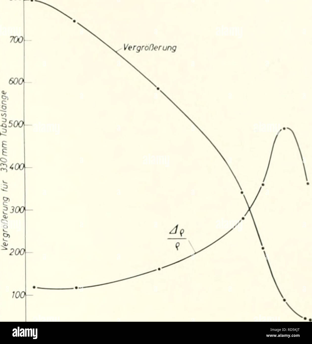
 . Electron microscopy; proceedings of the Stockholm Conference, September, 1956. Electron microscopy. ijjjj' "S*. J / = 3250 Amp., (J = 60 kV. Continuous variation of magnifi- cation between the three stage diffraction patterns and Amax = 28 000. Fig. 3. Cross section of a permanent magnetic microscope system. three-Stage diffraction patterns with different magni- fications. It is also possible to use the whole system as a diffraction condensor, and also to use it as an elec- tron shadow microscope. If crystalline matter is put into the caustic, dynamic diffraction patterns can be obtaine Stock Photohttps://www.alamy.com/image-license-details/?v=1https://www.alamy.com/electron-microscopy-proceedings-of-the-stockholm-conference-september-1956-electron-microscopy-ijjjj-quots-j-=-3250-amp-j-=-60-kv-continuous-variation-of-magnifi-cation-between-the-three-stage-diffraction-patterns-and-amax-=-28-000-fig-3-cross-section-of-a-permanent-magnetic-microscope-system-three-stage-diffraction-patterns-with-different-magni-fications-it-is-also-possible-to-use-the-whole-system-as-a-diffraction-condensor-and-also-to-use-it-as-an-elec-tron-shadow-microscope-if-crystalline-matter-is-put-into-the-caustic-dynamic-diffraction-patterns-can-be-obtaine-image231850494.html
RMRD5KJP–. Electron microscopy; proceedings of the Stockholm Conference, September, 1956. Electron microscopy. ijjjj' "S*. J / = 3250 Amp., (J = 60 kV. Continuous variation of magnifi- cation between the three stage diffraction patterns and Amax = 28 000. Fig. 3. Cross section of a permanent magnetic microscope system. three-Stage diffraction patterns with different magni- fications. It is also possible to use the whole system as a diffraction condensor, and also to use it as an elec- tron shadow microscope. If crystalline matter is put into the caustic, dynamic diffraction patterns can be obtaine
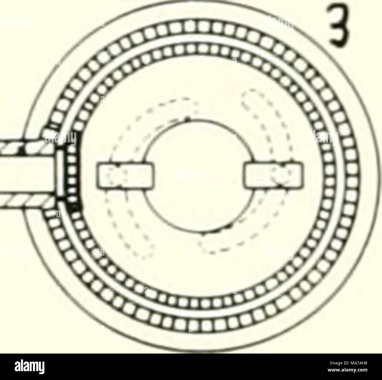 . Electron microscopy; proceedings of the Stockholm Conference, September, 1956 . ijjjj' "S*. J / = 3250 Amp., (J = 60 kV. Continuous variation of magnifi- cation between the three stage diffraction patterns and Amax = 28 000. Fig. 3. Cross section of a permanent magnetic microscope system. three-Stage diffraction patterns with different magni- fications. It is also possible to use the whole system as a diffraction condensor, and also to use it as an elec- tron shadow microscope. If crystalline matter is put into the caustic, dynamic diffraction patterns can be obtained which resemble Kik Stock Photohttps://www.alamy.com/image-license-details/?v=1https://www.alamy.com/electron-microscopy-proceedings-of-the-stockholm-conference-september-1956-ijjjj-quots-j-=-3250-amp-j-=-60-kv-continuous-variation-of-magnifi-cation-between-the-three-stage-diffraction-patterns-and-amax-=-28-000-fig-3-cross-section-of-a-permanent-magnetic-microscope-system-three-stage-diffraction-patterns-with-different-magni-fications-it-is-also-possible-to-use-the-whole-system-as-a-diffraction-condensor-and-also-to-use-it-as-an-elec-tron-shadow-microscope-if-crystalline-matter-is-put-into-the-caustic-dynamic-diffraction-patterns-can-be-obtained-which-resemble-kik-image178412228.html
RMMA7AH8–. Electron microscopy; proceedings of the Stockholm Conference, September, 1956 . ijjjj' "S*. J / = 3250 Amp., (J = 60 kV. Continuous variation of magnifi- cation between the three stage diffraction patterns and Amax = 28 000. Fig. 3. Cross section of a permanent magnetic microscope system. three-Stage diffraction patterns with different magni- fications. It is also possible to use the whole system as a diffraction condensor, and also to use it as an elec- tron shadow microscope. If crystalline matter is put into the caustic, dynamic diffraction patterns can be obtained which resemble Kik
 The electron microscope, its development, present performance and future possibilities electronmicrosco00gabo Year: 1948 Geometrical Electron Optics 11 transversal spherical aberration. In fact, the bundle has its smallest cross section not at p but at m, which is called the disc of minimum confusion. Its radius is one quarter of the spherical aberration. When an electron lens is focused, it is always m, not p, which is made to coincide with the screen or plate. Scherzer ^ has proved the important theorem that in electron lenses, whether electrostatic, magnetic, or combined, the spherical Stock Photohttps://www.alamy.com/image-license-details/?v=1https://www.alamy.com/the-electron-microscope-its-development-present-performance-and-future-possibilities-electronmicrosco00gabo-year-1948-geometrical-electron-optics-11-transversal-spherical-aberration-in-fact-the-bundle-has-its-smallest-cross-section-not-at-p-but-at-m-which-is-called-the-disc-of-minimum-confusion-its-radius-is-one-quarter-of-the-spherical-aberration-when-an-electron-lens-is-focused-it-is-always-m-not-p-which-is-made-to-coincide-with-the-screen-or-plate-scherzer-has-proved-the-important-theorem-that-in-electron-lenses-whether-electrostatic-magnetic-or-combined-the-spherical-image240662060.html
RMRYF2WG–The electron microscope, its development, present performance and future possibilities electronmicrosco00gabo Year: 1948 Geometrical Electron Optics 11 transversal spherical aberration. In fact, the bundle has its smallest cross section not at p but at m, which is called the disc of minimum confusion. Its radius is one quarter of the spherical aberration. When an electron lens is focused, it is always m, not p, which is made to coincide with the screen or plate. Scherzer ^ has proved the important theorem that in electron lenses, whether electrostatic, magnetic, or combined, the spherical
 . The electron microscope, its development, present performance and future possibilities. Electron microscopes. 10 The Electron Microscope Field linzs Ar = const.. / Lines A ^ consC (equivalent poteritial linesj Fig. 3. Magnetic lens This at once explains the lens effect of axially arranged coils. By its definition (3) the vectorpotential A is zero at the axis and increases approximately linearly with the radius r. This means that the equivalent potential decreases outside the axis and that the magnetic field has a repellent effect, i.e., it drives the elec- trons back, toward the axis. Theref Stock Photohttps://www.alamy.com/image-license-details/?v=1https://www.alamy.com/the-electron-microscope-its-development-present-performance-and-future-possibilities-electron-microscopes-10-the-electron-microscope-field-linzs-ar-=-const-lines-a-consc-equivalent-poteritial-linesj-fig-3-magnetic-lens-this-at-once-explains-the-lens-effect-of-axially-arranged-coils-by-its-definition-3-the-vectorpotential-a-is-zero-at-the-axis-and-increases-approximately-linearly-with-the-radius-r-this-means-that-the-equivalent-potential-decreases-outside-the-axis-and-that-the-magnetic-field-has-a-repellent-effect-ie-it-drives-the-elec-trons-back-toward-the-axis-theref-image231847517.html
RMRD5FTD–. The electron microscope, its development, present performance and future possibilities. Electron microscopes. 10 The Electron Microscope Field linzs Ar = const.. / Lines A ^ consC (equivalent poteritial linesj Fig. 3. Magnetic lens This at once explains the lens effect of axially arranged coils. By its definition (3) the vectorpotential A is zero at the axis and increases approximately linearly with the radius r. This means that the equivalent potential decreases outside the axis and that the magnetic field has a repellent effect, i.e., it drives the elec- trons back, toward the axis. Theref
 . The electron microscope, its development, present performance and future possibilities . I Photographic I / / / 4. Fig. 10 fact, most of the technique of these early microscopes originated in high voltage cathode ray oscillography, and the first instru- ment of Knoll and Ruska was a slightly modified oscillograph. (For the history of this development, cf. reference 2.) In a gas discharge tube, it is almost impossible to keep the voltage varia- tion below about 1 per cent; it was therefore a very essential step when this was replaced by a high vacuum—hot cathode discharge. The magnetic Stock Photohttps://www.alamy.com/image-license-details/?v=1https://www.alamy.com/the-electron-microscope-its-development-present-performance-and-future-possibilities-i-photographic-i-4-fig-10-fact-most-of-the-technique-of-these-early-microscopes-originated-in-high-voltage-cathode-ray-oscillography-and-the-first-instru-ment-of-knoll-and-ruska-was-a-slightly-modified-oscillograph-for-the-history-of-this-development-cf-reference-2-in-a-gas-discharge-tube-it-is-almost-impossible-to-keep-the-voltage-varia-tion-below-about-1-per-cent-it-was-therefore-a-very-essential-step-when-this-was-replaced-by-a-high-vacuumhot-cathode-discharge-the-magnetic-image178411742.html
RMMA79YX–. The electron microscope, its development, present performance and future possibilities . I Photographic I / / / 4. Fig. 10 fact, most of the technique of these early microscopes originated in high voltage cathode ray oscillography, and the first instru- ment of Knoll and Ruska was a slightly modified oscillograph. (For the history of this development, cf. reference 2.) In a gas discharge tube, it is almost impossible to keep the voltage varia- tion below about 1 per cent; it was therefore a very essential step when this was replaced by a high vacuum—hot cathode discharge. The magnetic
 The electron microscope, its development, The electron microscope, its development, present performance and future possibilities electronmicrosco00gabo Year: 1948 116 Tlie Electron Microscope stant is determined by the ratio beween electron injection and removal. If the removal is negligible, electrons will accumulate in the accessible space until they have depressed the potential at the inner radius to the level of the cathode potential. The inner radius itself moves outward during this accumulation, until it reaches the magnetic field line passing through the cathode. From this moment on, n Stock Photohttps://www.alamy.com/image-license-details/?v=1https://www.alamy.com/the-electron-microscope-its-development-the-electron-microscope-its-development-present-performance-and-future-possibilities-electronmicrosco00gabo-year-1948-116-tlie-electron-microscope-stant-is-determined-by-the-ratio-beween-electron-injection-and-removal-if-the-removal-is-negligible-electrons-will-accumulate-in-the-accessible-space-until-they-have-depressed-the-potential-at-the-inner-radius-to-the-level-of-the-cathode-potential-the-inner-radius-itself-moves-outward-during-this-accumulation-until-it-reaches-the-magnetic-field-line-passing-through-the-cathode-from-this-moment-on-n-image239595286.html
RMRWPE6E–The electron microscope, its development, The electron microscope, its development, present performance and future possibilities electronmicrosco00gabo Year: 1948 116 Tlie Electron Microscope stant is determined by the ratio beween electron injection and removal. If the removal is negligible, electrons will accumulate in the accessible space until they have depressed the potential at the inner radius to the level of the cathode potential. The inner radius itself moves outward during this accumulation, until it reaches the magnetic field line passing through the cathode. From this moment on, n
 . The electron microscope, its development, present performance and future possibilities. Electron microscopes. 66 The Electron Microscope tempted which would have entailed even the smallest sacrifice of performance. In spite of this an instrument was created, after an astonishingly short time of development, which can be suc- cessfully operated even by semi-skilled laboratory assistants; a fact which reflects the highest credit on the skill of the designers.. Fig. 17. Type B floor model and experimental desk model of R.C.A. magnetic microscopes Figure 18 is a schematic section of the microsco Stock Photohttps://www.alamy.com/image-license-details/?v=1https://www.alamy.com/the-electron-microscope-its-development-present-performance-and-future-possibilities-electron-microscopes-66-the-electron-microscope-tempted-which-would-have-entailed-even-the-smallest-sacrifice-of-performance-in-spite-of-this-an-instrument-was-created-after-an-astonishingly-short-time-of-development-which-can-be-suc-cessfully-operated-even-by-semi-skilled-laboratory-assistants-a-fact-which-reflects-the-highest-credit-on-the-skill-of-the-designers-fig-17-type-b-floor-model-and-experimental-desk-model-of-rca-magnetic-microscopes-figure-18-is-a-schematic-section-of-the-microsco-image231847485.html
RMRD5FR9–. The electron microscope, its development, present performance and future possibilities. Electron microscopes. 66 The Electron Microscope tempted which would have entailed even the smallest sacrifice of performance. In spite of this an instrument was created, after an astonishingly short time of development, which can be suc- cessfully operated even by semi-skilled laboratory assistants; a fact which reflects the highest credit on the skill of the designers.. Fig. 17. Type B floor model and experimental desk model of R.C.A. magnetic microscopes Figure 18 is a schematic section of the microsco
 . The electron microscope, its development, present performance and future possibilities . Fig. 12. Design of magnetic objective (E. Ruska, 1934) If these electrons are ultimately accelerated by v volts 11,600 the root mean square divergence is 82 — ^ 11,600 ^ J In the case of a tungsten cathode with T = 2,600°K and V = 60,000 volts this is very nearly 2.0r^. Whenever the cathode is imaged on the specimen, the di- vergence cannot be less than this value, though it can be more, as a consequence of lens errors and space charge effects. But this divergence, small as it appears, is of the order Stock Photohttps://www.alamy.com/image-license-details/?v=1https://www.alamy.com/the-electron-microscope-its-development-present-performance-and-future-possibilities-fig-12-design-of-magnetic-objective-e-ruska-1934-if-these-electrons-are-ultimately-accelerated-by-v-volts-11600-the-root-mean-square-divergence-is-82-11600-j-in-the-case-of-a-tungsten-cathode-with-t-=-2600k-and-v-=-60000-volts-this-is-very-nearly-20r-whenever-the-cathode-is-imaged-on-the-specimen-the-di-vergence-cannot-be-less-than-this-value-though-it-can-be-more-as-a-consequence-of-lens-errors-and-space-charge-effects-but-this-divergence-small-as-it-appears-is-of-the-order-image178411754.html
RMMA7A0A–. The electron microscope, its development, present performance and future possibilities . Fig. 12. Design of magnetic objective (E. Ruska, 1934) If these electrons are ultimately accelerated by v volts 11,600 the root mean square divergence is 82 — ^ 11,600 ^ J In the case of a tungsten cathode with T = 2,600°K and V = 60,000 volts this is very nearly 2.0r^. Whenever the cathode is imaged on the specimen, the di- vergence cannot be less than this value, though it can be more, as a consequence of lens errors and space charge effects. But this divergence, small as it appears, is of the order
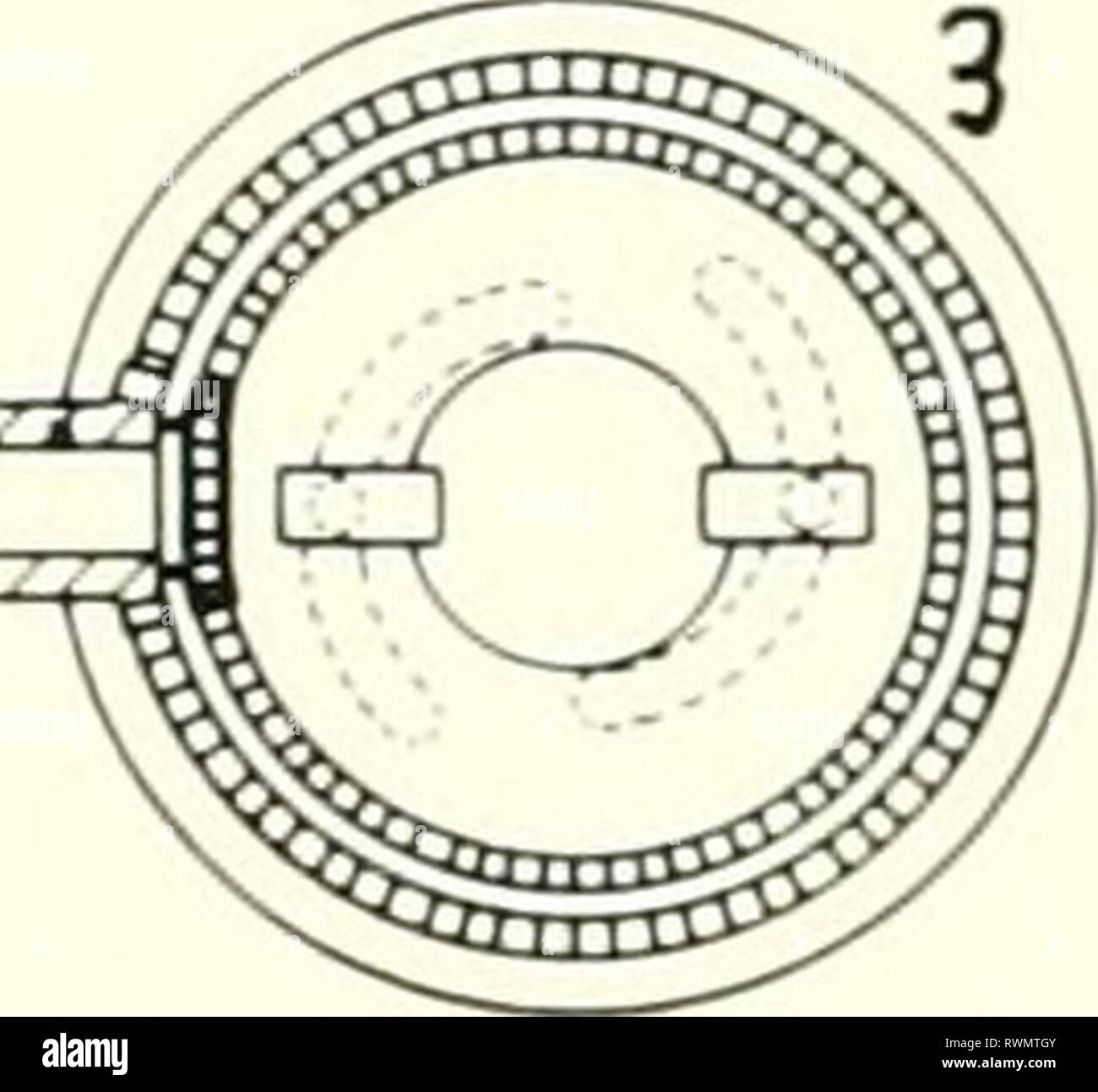 Electron microscopy; proceedings of the Electron microscopy; proceedings of the Stockholm Conference, September, 1956 electronmicrosco00euro Year: 1957 ijjjj' 'S*. J / = 3250 Amp., (J = 60 kV. Continuous variation of magnifi- cation between the three stage diffraction patterns and Amax = 28 000. Fig. 3. Cross section of a permanent magnetic microscope system. three-Stage diffraction patterns with different magni- fications. It is also possible to use the whole system as a diffraction condensor, and also to use it as an elec- tron shadow microscope. If crystalline matter is put into the causti Stock Photohttps://www.alamy.com/image-license-details/?v=1https://www.alamy.com/electron-microscopy-proceedings-of-the-electron-microscopy-proceedings-of-the-stockholm-conference-september-1956-electronmicrosco00euro-year-1957-ijjjj-s-j-=-3250-amp-j-=-60-kv-continuous-variation-of-magnifi-cation-between-the-three-stage-diffraction-patterns-and-amax-=-28-000-fig-3-cross-section-of-a-permanent-magnetic-microscope-system-three-stage-diffraction-patterns-with-different-magni-fications-it-is-also-possible-to-use-the-whole-system-as-a-diffraction-condensor-and-also-to-use-it-as-an-elec-tron-shadow-microscope-if-crystalline-matter-is-put-into-the-causti-image239559515.html
RMRWMTGY–Electron microscopy; proceedings of the Electron microscopy; proceedings of the Stockholm Conference, September, 1956 electronmicrosco00euro Year: 1957 ijjjj' 'S*. J / = 3250 Amp., (J = 60 kV. Continuous variation of magnifi- cation between the three stage diffraction patterns and Amax = 28 000. Fig. 3. Cross section of a permanent magnetic microscope system. three-Stage diffraction patterns with different magni- fications. It is also possible to use the whole system as a diffraction condensor, and also to use it as an elec- tron shadow microscope. If crystalline matter is put into the causti
 . The electron microscope, its development, present performance and future possibilities. Electron microscopes. Supermicroscopes 35. Fig. 12. Design of magnetic objective (E. Ruska, 1934) If these electrons are ultimately accelerated by v volts 11,600 the root mean square divergence is 82 — ^ 11,600 ^ J In the case of a tungsten cathode with T = 2,600°K and V = 60,000 volts this is very nearly 2.0r^. Whenever the cathode is imaged on the specimen, the di- vergence cannot be less than this value, though it can be more, as a consequence of lens errors and space charge effects. But this diverge Stock Photohttps://www.alamy.com/image-license-details/?v=1https://www.alamy.com/the-electron-microscope-its-development-present-performance-and-future-possibilities-electron-microscopes-supermicroscopes-35-fig-12-design-of-magnetic-objective-e-ruska-1934-if-these-electrons-are-ultimately-accelerated-by-v-volts-11600-the-root-mean-square-divergence-is-82-11600-j-in-the-case-of-a-tungsten-cathode-with-t-=-2600k-and-v-=-60000-volts-this-is-very-nearly-20r-whenever-the-cathode-is-imaged-on-the-specimen-the-di-vergence-cannot-be-less-than-this-value-though-it-can-be-more-as-a-consequence-of-lens-errors-and-space-charge-effects-but-this-diverge-image231847500.html
RMRD5FRT–. The electron microscope, its development, present performance and future possibilities. Electron microscopes. Supermicroscopes 35. Fig. 12. Design of magnetic objective (E. Ruska, 1934) If these electrons are ultimately accelerated by v volts 11,600 the root mean square divergence is 82 — ^ 11,600 ^ J In the case of a tungsten cathode with T = 2,600°K and V = 60,000 volts this is very nearly 2.0r^. Whenever the cathode is imaged on the specimen, the di- vergence cannot be less than this value, though it can be more, as a consequence of lens errors and space charge effects. But this diverge
![. The electron microscope, its development, present performance and future possibilities . Fig. 2. Electron trajectories in magnetic lens. Curves orthogonal to the trajectories are drawn to show the variation of the pitch The magnetic field lines, i.e., the meridian curves of the tubes which carry a constant flux ]I have therefore equations rA =^ const. Their shape is shown in an example in the upper part of figure 3. The equation (2) becomes now e r(mvt — —A) = const. (4) The expression in brackets can be interpreted as the total momentum of the electron in the magnetic field. It consists of Stock Photo . The electron microscope, its development, present performance and future possibilities . Fig. 2. Electron trajectories in magnetic lens. Curves orthogonal to the trajectories are drawn to show the variation of the pitch The magnetic field lines, i.e., the meridian curves of the tubes which carry a constant flux ]I have therefore equations rA =^ const. Their shape is shown in an example in the upper part of figure 3. The equation (2) becomes now e r(mvt — —A) = const. (4) The expression in brackets can be interpreted as the total momentum of the electron in the magnetic field. It consists of Stock Photo](https://c8.alamy.com/comp/MA7A12/the-electron-microscope-its-development-present-performance-and-future-possibilities-fig-2-electron-trajectories-in-magnetic-lens-curves-orthogonal-to-the-trajectories-are-drawn-to-show-the-variation-of-the-pitch-the-magnetic-field-lines-ie-the-meridian-curves-of-the-tubes-which-carry-a-constant-flux-i-have-therefore-equations-ra-=-const-their-shape-is-shown-in-an-example-in-the-upper-part-of-figure-3-the-equation-2-becomes-now-e-rmvt-a-=-const-4-the-expression-in-brackets-can-be-interpreted-as-the-total-momentum-of-the-electron-in-the-magnetic-field-it-consists-of-MA7A12.jpg) . The electron microscope, its development, present performance and future possibilities . Fig. 2. Electron trajectories in magnetic lens. Curves orthogonal to the trajectories are drawn to show the variation of the pitch The magnetic field lines, i.e., the meridian curves of the tubes which carry a constant flux ]I have therefore equations rA =^ const. Their shape is shown in an example in the upper part of figure 3. The equation (2) becomes now e r(mvt — —A) = const. (4) The expression in brackets can be interpreted as the total momentum of the electron in the magnetic field. It consists of Stock Photohttps://www.alamy.com/image-license-details/?v=1https://www.alamy.com/the-electron-microscope-its-development-present-performance-and-future-possibilities-fig-2-electron-trajectories-in-magnetic-lens-curves-orthogonal-to-the-trajectories-are-drawn-to-show-the-variation-of-the-pitch-the-magnetic-field-lines-ie-the-meridian-curves-of-the-tubes-which-carry-a-constant-flux-i-have-therefore-equations-ra-=-const-their-shape-is-shown-in-an-example-in-the-upper-part-of-figure-3-the-equation-2-becomes-now-e-rmvt-a-=-const-4-the-expression-in-brackets-can-be-interpreted-as-the-total-momentum-of-the-electron-in-the-magnetic-field-it-consists-of-image178411774.html
. The electron microscope, its development, present performance and future possibilities . Fig. 2. Electron trajectories in magnetic lens. Curves orthogonal to the trajectories are drawn to show the variation of the pitch The magnetic field lines, i.e., the meridian curves of the tubes which carry a constant flux ]I have therefore equations rA =^ const. Their shape is shown in an example in the upper part of figure 3. The equation (2) becomes now e r(mvt — —A) = const. (4) The expression in brackets can be interpreted as the total momentum of the electron in the magnetic field. It consists of Stock Photohttps://www.alamy.com/image-license-details/?v=1https://www.alamy.com/the-electron-microscope-its-development-present-performance-and-future-possibilities-fig-2-electron-trajectories-in-magnetic-lens-curves-orthogonal-to-the-trajectories-are-drawn-to-show-the-variation-of-the-pitch-the-magnetic-field-lines-ie-the-meridian-curves-of-the-tubes-which-carry-a-constant-flux-i-have-therefore-equations-ra-=-const-their-shape-is-shown-in-an-example-in-the-upper-part-of-figure-3-the-equation-2-becomes-now-e-rmvt-a-=-const-4-the-expression-in-brackets-can-be-interpreted-as-the-total-momentum-of-the-electron-in-the-magnetic-field-it-consists-of-image178411774.htmlRMMA7A12–. The electron microscope, its development, present performance and future possibilities . Fig. 2. Electron trajectories in magnetic lens. Curves orthogonal to the trajectories are drawn to show the variation of the pitch The magnetic field lines, i.e., the meridian curves of the tubes which carry a constant flux ]I have therefore equations rA =^ const. Their shape is shown in an example in the upper part of figure 3. The equation (2) becomes now e r(mvt — —A) = const. (4) The expression in brackets can be interpreted as the total momentum of the electron in the magnetic field. It consists of
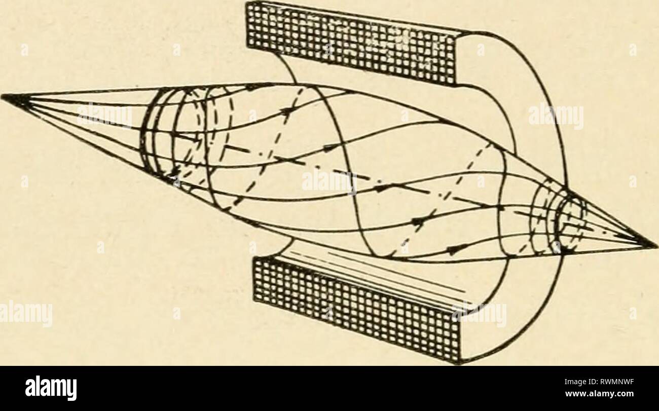 The electron microscope, its development, The electron microscope, its development, present performance and future possibilities electronmicrosco00gabo Year: 1948 8 The Electron Microscope That is, the angular momentum changes proportionally to the magnetic flux which passes between the tzvo coaxial circles drawn through the initial and final positions respectively. This result can be put into an even simpler form if we intro- duce the vectorpotential A, from which the vector H of the magnetic field intensity can be derived by the operation H = curl A. In the case of axially symmetrical field Stock Photohttps://www.alamy.com/image-license-details/?v=1https://www.alamy.com/the-electron-microscope-its-development-the-electron-microscope-its-development-present-performance-and-future-possibilities-electronmicrosco00gabo-year-1948-8-the-electron-microscope-that-is-the-angular-momentum-changes-proportionally-to-the-magnetic-flux-which-passes-between-the-tzvo-coaxial-circles-drawn-through-the-initial-and-final-positions-respectively-this-result-can-be-put-into-an-even-simpler-form-if-we-intro-duce-the-vectorpotential-a-from-which-the-vector-h-of-the-magnetic-field-intensity-can-be-derived-by-the-operation-h-=-curl-a-in-the-case-of-axially-symmetrical-field-image239557403.html
RMRWMNWF–The electron microscope, its development, The electron microscope, its development, present performance and future possibilities electronmicrosco00gabo Year: 1948 8 The Electron Microscope That is, the angular momentum changes proportionally to the magnetic flux which passes between the tzvo coaxial circles drawn through the initial and final positions respectively. This result can be put into an even simpler form if we intro- duce the vectorpotential A, from which the vector H of the magnetic field intensity can be derived by the operation H = curl A. In the case of axially symmetrical field
 . Electron microscopy; proceedings of the Stockholm Conference, September, 1956. Electron microscopy. Strahlnchtung 1, Permanent magnet. 2a, 2b, Disploceable polepieces of the intermediate lens. 3, Insert, at the same time fixed pole- piece at the final projector lens. 4, Disploceable polepiece of the fmal projector lens. 5, Control nut. 6, Bevel gear. Fig. 1. Cross section through a two-stage projective system operating with permanent magnets. an electron microscope objective lens a permanent magnetic einzel-lens may be used. On its electron optical properties Lenz (9) has published a paper. Stock Photohttps://www.alamy.com/image-license-details/?v=1https://www.alamy.com/electron-microscopy-proceedings-of-the-stockholm-conference-september-1956-electron-microscopy-strahlnchtung-1-permanent-magnet-2a-2b-disploceable-polepieces-of-the-intermediate-lens-3-insert-at-the-same-time-fixed-pole-piece-at-the-final-projector-lens-4-disploceable-polepiece-of-the-fmal-projector-lens-5-control-nut-6-bevel-gear-fig-1-cross-section-through-a-two-stage-projective-system-operating-with-permanent-magnets-an-electron-microscope-objective-lens-a-permanent-magnetic-einzel-lens-may-be-used-on-its-electron-optical-properties-lenz-9-has-published-a-paper-image231850496.html
RMRD5KJT–. Electron microscopy; proceedings of the Stockholm Conference, September, 1956. Electron microscopy. Strahlnchtung 1, Permanent magnet. 2a, 2b, Disploceable polepieces of the intermediate lens. 3, Insert, at the same time fixed pole- piece at the final projector lens. 4, Disploceable polepiece of the fmal projector lens. 5, Control nut. 6, Bevel gear. Fig. 1. Cross section through a two-stage projective system operating with permanent magnets. an electron microscope objective lens a permanent magnetic einzel-lens may be used. On its electron optical properties Lenz (9) has published a paper.
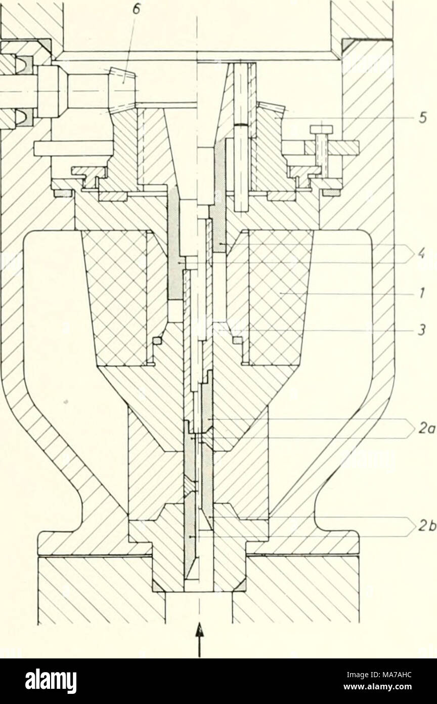 . Electron microscopy; proceedings of the Stockholm Conference, September, 1956 . Strahlnchtung 1, Permanent magnet. 2a, 2b, Disploceable polepieces of the intermediate lens. 3, Insert, at the same time fixed pole- piece at the final projector lens. 4, Disploceable polepiece of the fmal projector lens. 5, Control nut. 6, Bevel gear. Fig. 1. Cross section through a two-stage projective system operating with permanent magnets. an electron microscope objective lens a permanent magnetic einzel-lens may be used. On its electron optical properties Lenz (9) has published a paper. Such einzel-lenses a Stock Photohttps://www.alamy.com/image-license-details/?v=1https://www.alamy.com/electron-microscopy-proceedings-of-the-stockholm-conference-september-1956-strahlnchtung-1-permanent-magnet-2a-2b-disploceable-polepieces-of-the-intermediate-lens-3-insert-at-the-same-time-fixed-pole-piece-at-the-final-projector-lens-4-disploceable-polepiece-of-the-fmal-projector-lens-5-control-nut-6-bevel-gear-fig-1-cross-section-through-a-two-stage-projective-system-operating-with-permanent-magnets-an-electron-microscope-objective-lens-a-permanent-magnetic-einzel-lens-may-be-used-on-its-electron-optical-properties-lenz-9-has-published-a-paper-such-einzel-lenses-a-image178412232.html
RMMA7AHC–. Electron microscopy; proceedings of the Stockholm Conference, September, 1956 . Strahlnchtung 1, Permanent magnet. 2a, 2b, Disploceable polepieces of the intermediate lens. 3, Insert, at the same time fixed pole- piece at the final projector lens. 4, Disploceable polepiece of the fmal projector lens. 5, Control nut. 6, Bevel gear. Fig. 1. Cross section through a two-stage projective system operating with permanent magnets. an electron microscope objective lens a permanent magnetic einzel-lens may be used. On its electron optical properties Lenz (9) has published a paper. Such einzel-lenses a
 The electron microscope, its development, present performance and future possibilities electronmicrosco00gabo Year: 1948 8 The Electron Microscope That is, the angular momentum changes proportionally to the magnetic flux which passes between the tzvo coaxial circles drawn through the initial and final positions respectively. This result can be put into an even simpler form if we intro- duce the vectorpotential A, from which the vector H of the magnetic field intensity can be derived by the operation H = curl A. In the case of axially symmetrical fields the vector A has always tangential dire Stock Photohttps://www.alamy.com/image-license-details/?v=1https://www.alamy.com/the-electron-microscope-its-development-present-performance-and-future-possibilities-electronmicrosco00gabo-year-1948-8-the-electron-microscope-that-is-the-angular-momentum-changes-proportionally-to-the-magnetic-flux-which-passes-between-the-tzvo-coaxial-circles-drawn-through-the-initial-and-final-positions-respectively-this-result-can-be-put-into-an-even-simpler-form-if-we-intro-duce-the-vectorpotential-a-from-which-the-vector-h-of-the-magnetic-field-intensity-can-be-derived-by-the-operation-h-=-curl-a-in-the-case-of-axially-symmetrical-fields-the-vector-a-has-always-tangential-dire-image240661196.html
RMRYF1PM–The electron microscope, its development, present performance and future possibilities electronmicrosco00gabo Year: 1948 8 The Electron Microscope That is, the angular momentum changes proportionally to the magnetic flux which passes between the tzvo coaxial circles drawn through the initial and final positions respectively. This result can be put into an even simpler form if we intro- duce the vectorpotential A, from which the vector H of the magnetic field intensity can be derived by the operation H = curl A. In the case of axially symmetrical fields the vector A has always tangential dire
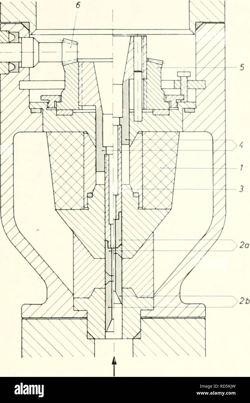 . Electron microscopy; proceedings of the Stockholm Conference, September, 1956. Electron microscopy. Imaging Elemenls with Permanent Magnets 15 ^gS ^ ^m:. Strahlnchtung 1, Permanent magnet. 2a, 2b, Disploceable polepieces of the intermediate lens. 3, Insert, at the same time fixed pole- piece at the final projector lens. 4, Disploceable polepiece of the fmal projector lens. 5, Control nut. 6, Bevel gear. Fig. 1. Cross section through a two-stage projective system operating with permanent magnets. an electron microscope objective lens a permanent magnetic einzel-lens may be used. On its electr Stock Photohttps://www.alamy.com/image-license-details/?v=1https://www.alamy.com/electron-microscopy-proceedings-of-the-stockholm-conference-september-1956-electron-microscopy-imaging-elemenls-with-permanent-magnets-15-gs-m-strahlnchtung-1-permanent-magnet-2a-2b-disploceable-polepieces-of-the-intermediate-lens-3-insert-at-the-same-time-fixed-pole-piece-at-the-final-projector-lens-4-disploceable-polepiece-of-the-fmal-projector-lens-5-control-nut-6-bevel-gear-fig-1-cross-section-through-a-two-stage-projective-system-operating-with-permanent-magnets-an-electron-microscope-objective-lens-a-permanent-magnetic-einzel-lens-may-be-used-on-its-electr-image231850497.html
RMRD5KJW–. Electron microscopy; proceedings of the Stockholm Conference, September, 1956. Electron microscopy. Imaging Elemenls with Permanent Magnets 15 ^gS ^ ^m:. Strahlnchtung 1, Permanent magnet. 2a, 2b, Disploceable polepieces of the intermediate lens. 3, Insert, at the same time fixed pole- piece at the final projector lens. 4, Disploceable polepiece of the fmal projector lens. 5, Control nut. 6, Bevel gear. Fig. 1. Cross section through a two-stage projective system operating with permanent magnets. an electron microscope objective lens a permanent magnetic einzel-lens may be used. On its electr
 The electron microscope, its development, The electron microscope, its development, present performance and future possibilities electronmicrosco00gabo Year: 1948 10 The Electron Microscope Field linzs Ar = const. / Lines A ^ consC (equivalent poteritial linesj Fig. 3. Magnetic lens This at once explains the lens effect of axially arranged coils. By its definition (3) the vectorpotential A is zero at the axis and increases approximately linearly with the radius r. This means that the equivalent potential decreases outside the axis and that the magnetic field has a repellent effect, i.e., i Stock Photohttps://www.alamy.com/image-license-details/?v=1https://www.alamy.com/the-electron-microscope-its-development-the-electron-microscope-its-development-present-performance-and-future-possibilities-electronmicrosco00gabo-year-1948-10-the-electron-microscope-field-linzs-ar-=-const-lines-a-consc-equivalent-poteritial-linesj-fig-3-magnetic-lens-this-at-once-explains-the-lens-effect-of-axially-arranged-coils-by-its-definition-3-the-vectorpotential-a-is-zero-at-the-axis-and-increases-approximately-linearly-with-the-radius-r-this-means-that-the-equivalent-potential-decreases-outside-the-axis-and-that-the-magnetic-field-has-a-repellent-effect-ie-i-image239557705.html
RMRWMP89–The electron microscope, its development, The electron microscope, its development, present performance and future possibilities electronmicrosco00gabo Year: 1948 10 The Electron Microscope Field linzs Ar = const. / Lines A ^ consC (equivalent poteritial linesj Fig. 3. Magnetic lens This at once explains the lens effect of axially arranged coils. By its definition (3) the vectorpotential A is zero at the axis and increases approximately linearly with the radius r. This means that the equivalent potential decreases outside the axis and that the magnetic field has a repellent effect, i.e., i
 The electron microscope, its development, The electron microscope, its development, present performance and future possibilities electronmicrosco00gabo Year: 1948 66 The Electron Microscope tempted which would have entailed even the smallest sacrifice of performance. In spite of this an instrument was created, after an astonishingly short time of development, which can be suc- cessfully operated even by semi-skilled laboratory assistants; a fact which reflects the highest credit on the skill of the designers. Fig. 17. Type B floor model and experimental desk model of R.C.A. magnetic micros Stock Photohttps://www.alamy.com/image-license-details/?v=1https://www.alamy.com/the-electron-microscope-its-development-the-electron-microscope-its-development-present-performance-and-future-possibilities-electronmicrosco00gabo-year-1948-66-the-electron-microscope-tempted-which-would-have-entailed-even-the-smallest-sacrifice-of-performance-in-spite-of-this-an-instrument-was-created-after-an-astonishingly-short-time-of-development-which-can-be-suc-cessfully-operated-even-by-semi-skilled-laboratory-assistants-a-fact-which-reflects-the-highest-credit-on-the-skill-of-the-designers-fig-17-type-b-floor-model-and-experimental-desk-model-of-rca-magnetic-micros-image239577870.html
RMRWNM0E–The electron microscope, its development, The electron microscope, its development, present performance and future possibilities electronmicrosco00gabo Year: 1948 66 The Electron Microscope tempted which would have entailed even the smallest sacrifice of performance. In spite of this an instrument was created, after an astonishingly short time of development, which can be suc- cessfully operated even by semi-skilled laboratory assistants; a fact which reflects the highest credit on the skill of the designers. Fig. 17. Type B floor model and experimental desk model of R.C.A. magnetic micros
 The electron microscope, its development, present performance and future possibilities electronmicrosco00gabo Year: 1948 10 The Electron Microscope Field linzs Ar = const. / Lines A ^ consC (equivalent poteritial linesj Fig. 3. Magnetic lens This at once explains the lens effect of axially arranged coils. By its definition (3) the vectorpotential A is zero at the axis and increases approximately linearly with the radius r. This means that the equivalent potential decreases outside the axis and that the magnetic field has a repellent effect, i.e., it drives the elec- trons back, toward the Stock Photohttps://www.alamy.com/image-license-details/?v=1https://www.alamy.com/the-electron-microscope-its-development-present-performance-and-future-possibilities-electronmicrosco00gabo-year-1948-10-the-electron-microscope-field-linzs-ar-=-const-lines-a-consc-equivalent-poteritial-linesj-fig-3-magnetic-lens-this-at-once-explains-the-lens-effect-of-axially-arranged-coils-by-its-definition-3-the-vectorpotential-a-is-zero-at-the-axis-and-increases-approximately-linearly-with-the-radius-r-this-means-that-the-equivalent-potential-decreases-outside-the-axis-and-that-the-magnetic-field-has-a-repellent-effect-ie-it-drives-the-elec-trons-back-toward-the-image240661717.html
RMRYF2D9–The electron microscope, its development, present performance and future possibilities electronmicrosco00gabo Year: 1948 10 The Electron Microscope Field linzs Ar = const. / Lines A ^ consC (equivalent poteritial linesj Fig. 3. Magnetic lens This at once explains the lens effect of axially arranged coils. By its definition (3) the vectorpotential A is zero at the axis and increases approximately linearly with the radius r. This means that the equivalent potential decreases outside the axis and that the magnetic field has a repellent effect, i.e., it drives the elec- trons back, toward the
 The electron microscope, its development, The electron microscope, its development, present performance and future possibilities electronmicrosco00gabo Year: 1948 Possibilities of Future Development 111 potential lens is connected with the cathode as usual, whereas the outer electrode, preferably earthed, is formed by.the pole pieces of the magnetic lens. The object is placed outside this lens, shielded from the strong electrostatic fields by an apertured diaphragm. The focal length of this first lens is supposed to be of the same order as in present-day microscopes, i.e., about 0.5 cm for 60 Stock Photohttps://www.alamy.com/image-license-details/?v=1https://www.alamy.com/the-electron-microscope-its-development-the-electron-microscope-its-development-present-performance-and-future-possibilities-electronmicrosco00gabo-year-1948-possibilities-of-future-development-111-potential-lens-is-connected-with-the-cathode-as-usual-whereas-the-outer-electrode-preferably-earthed-is-formed-bythe-pole-pieces-of-the-magnetic-lens-the-object-is-placed-outside-this-lens-shielded-from-the-strong-electrostatic-fields-by-an-apertured-diaphragm-the-focal-length-of-this-first-lens-is-supposed-to-be-of-the-same-order-as-in-present-day-microscopes-ie-about-05-cm-for-60-image239594631.html
RMRWPDB3–The electron microscope, its development, The electron microscope, its development, present performance and future possibilities electronmicrosco00gabo Year: 1948 Possibilities of Future Development 111 potential lens is connected with the cathode as usual, whereas the outer electrode, preferably earthed, is formed by.the pole pieces of the magnetic lens. The object is placed outside this lens, shielded from the strong electrostatic fields by an apertured diaphragm. The focal length of this first lens is supposed to be of the same order as in present-day microscopes, i.e., about 0.5 cm for 60
 The electron microscope, its development, present performance and future possibilities electronmicrosco00gabo Year: 1948 66 The Electron Microscope tempted which would have entailed even the smallest sacrifice of performance. In spite of this an instrument was created, after an astonishingly short time of development, which can be suc- cessfully operated even by semi-skilled laboratory assistants; a fact which reflects the highest credit on the skill of the designers. Fig. 17. Type B floor model and experimental desk model of R.C.A. magnetic microscopes Figure 18 is a schematic section of Stock Photohttps://www.alamy.com/image-license-details/?v=1https://www.alamy.com/the-electron-microscope-its-development-present-performance-and-future-possibilities-electronmicrosco00gabo-year-1948-66-the-electron-microscope-tempted-which-would-have-entailed-even-the-smallest-sacrifice-of-performance-in-spite-of-this-an-instrument-was-created-after-an-astonishingly-short-time-of-development-which-can-be-suc-cessfully-operated-even-by-semi-skilled-laboratory-assistants-a-fact-which-reflects-the-highest-credit-on-the-skill-of-the-designers-fig-17-type-b-floor-model-and-experimental-desk-model-of-rca-magnetic-microscopes-figure-18-is-a-schematic-section-of-image240705696.html
RMRYH2G0–The electron microscope, its development, present performance and future possibilities electronmicrosco00gabo Year: 1948 66 The Electron Microscope tempted which would have entailed even the smallest sacrifice of performance. In spite of this an instrument was created, after an astonishingly short time of development, which can be suc- cessfully operated even by semi-skilled laboratory assistants; a fact which reflects the highest credit on the skill of the designers. Fig. 17. Type B floor model and experimental desk model of R.C.A. magnetic microscopes Figure 18 is a schematic section of
 Electron microscopy; proceedings of the Stockholm Conference, September, 1956 electronmicrosco00euro Year: 1957 ijjjj' 'S*. J / = 3250 Amp., (J = 60 kV. Continuous variation of magnifi- cation between the three stage diffraction patterns and Amax = 28 000. Fig. 3. Cross section of a permanent magnetic microscope system. three-Stage diffraction patterns with different magni- fications. It is also possible to use the whole system as a diffraction condensor, and also to use it as an elec- tron shadow microscope. If crystalline matter is put into the caustic, dynamic diffraction patterns can b Stock Photohttps://www.alamy.com/image-license-details/?v=1https://www.alamy.com/electron-microscopy-proceedings-of-the-stockholm-conference-september-1956-electronmicrosco00euro-year-1957-ijjjj-s-j-=-3250-amp-j-=-60-kv-continuous-variation-of-magnifi-cation-between-the-three-stage-diffraction-patterns-and-amax-=-28-000-fig-3-cross-section-of-a-permanent-magnetic-microscope-system-three-stage-diffraction-patterns-with-different-magni-fications-it-is-also-possible-to-use-the-whole-system-as-a-diffraction-condensor-and-also-to-use-it-as-an-elec-tron-shadow-microscope-if-crystalline-matter-is-put-into-the-caustic-dynamic-diffraction-patterns-can-b-image240663330.html
RMRYF4EX–Electron microscopy; proceedings of the Stockholm Conference, September, 1956 electronmicrosco00euro Year: 1957 ijjjj' 'S*. J / = 3250 Amp., (J = 60 kV. Continuous variation of magnifi- cation between the three stage diffraction patterns and Amax = 28 000. Fig. 3. Cross section of a permanent magnetic microscope system. three-Stage diffraction patterns with different magni- fications. It is also possible to use the whole system as a diffraction condensor, and also to use it as an elec- tron shadow microscope. If crystalline matter is put into the caustic, dynamic diffraction patterns can b
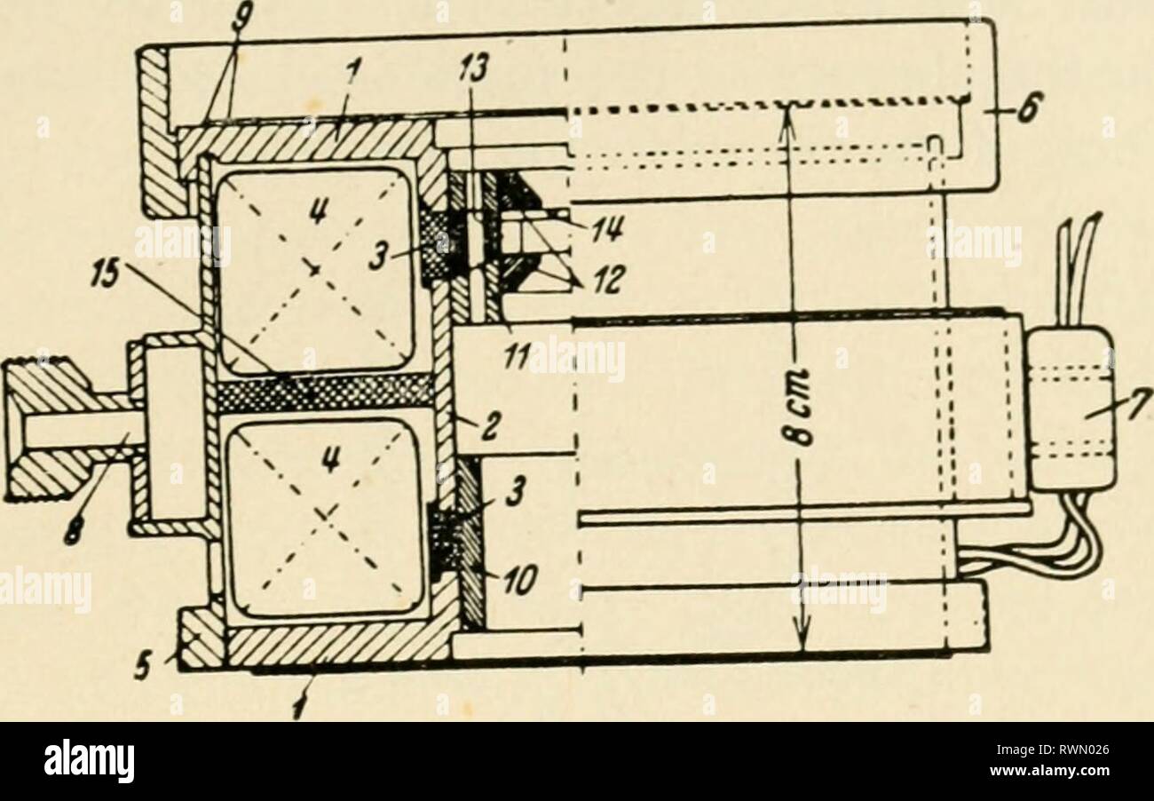 The electron microscope, its development, The electron microscope, its development, present performance and future possibilities electronmicrosco00gabo Year: 1948 Supermicroscopes 35 Fig. 12. Design of magnetic objective (E. Ruska, 1934) If these electrons are ultimately accelerated by v volts 11,600 the root mean square divergence is 82 — ^ 11,600 ^ J In the case of a tungsten cathode with T = 2,600°K and V = 60,000 volts this is very nearly 2.0r^. Whenever the cathode is imaged on the specimen, the di- vergence cannot be less than this value, though it can be more, as a consequence of Stock Photohttps://www.alamy.com/image-license-details/?v=1https://www.alamy.com/the-electron-microscope-its-development-the-electron-microscope-its-development-present-performance-and-future-possibilities-electronmicrosco00gabo-year-1948-supermicroscopes-35-fig-12-design-of-magnetic-objective-e-ruska-1934-if-these-electrons-are-ultimately-accelerated-by-v-volts-11600-the-root-mean-square-divergence-is-82-11600-j-in-the-case-of-a-tungsten-cathode-with-t-=-2600k-and-v-=-60000-volts-this-is-very-nearly-20r-whenever-the-cathode-is-imaged-on-the-specimen-the-di-vergence-cannot-be-less-than-this-value-though-it-can-be-more-as-a-consequence-of-image239562238.html
RMRWN026–The electron microscope, its development, The electron microscope, its development, present performance and future possibilities electronmicrosco00gabo Year: 1948 Supermicroscopes 35 Fig. 12. Design of magnetic objective (E. Ruska, 1934) If these electrons are ultimately accelerated by v volts 11,600 the root mean square divergence is 82 — ^ 11,600 ^ J In the case of a tungsten cathode with T = 2,600°K and V = 60,000 volts this is very nearly 2.0r^. Whenever the cathode is imaged on the specimen, the di- vergence cannot be less than this value, though it can be more, as a consequence of
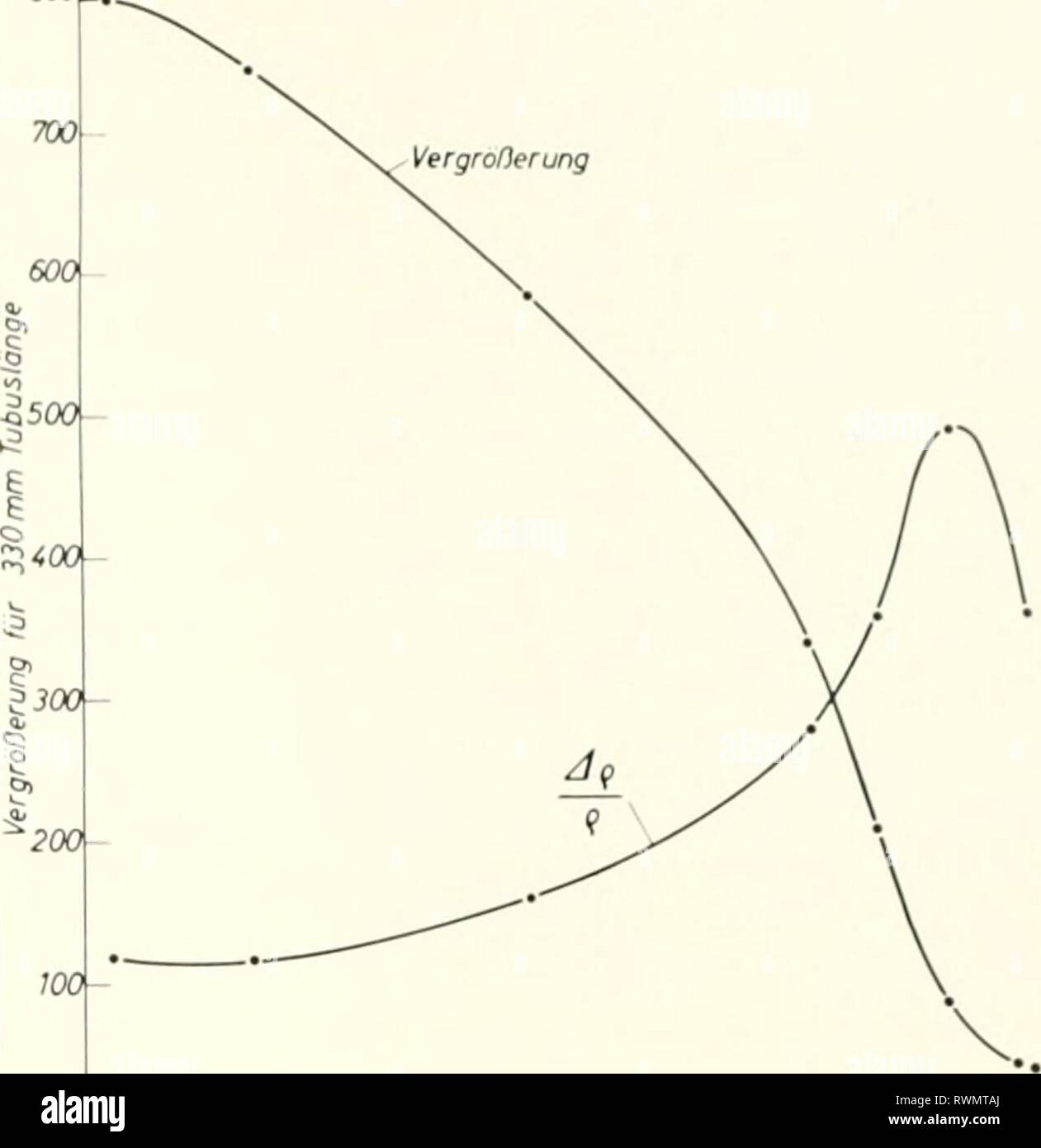 Electron microscopy; proceedings of the Electron microscopy; proceedings of the Stockholm Conference, September, 1956 electronmicrosco00euro Year: 1957 Strahlnchtung 1, Permanent magnet. 2a, 2b, Disploceable polepieces of the intermediate lens. 3, Insert, at the same time fixed pole- piece at the final projector lens. 4, Disploceable polepiece of the fmal projector lens. 5, Control nut. 6, Bevel gear. Fig. 1. Cross section through a two-stage projective system operating with permanent magnets. an electron microscope objective lens a permanent magnetic einzel-lens may be used. On its electron Stock Photohttps://www.alamy.com/image-license-details/?v=1https://www.alamy.com/electron-microscopy-proceedings-of-the-electron-microscopy-proceedings-of-the-stockholm-conference-september-1956-electronmicrosco00euro-year-1957-strahlnchtung-1-permanent-magnet-2a-2b-disploceable-polepieces-of-the-intermediate-lens-3-insert-at-the-same-time-fixed-pole-piece-at-the-final-projector-lens-4-disploceable-polepiece-of-the-fmal-projector-lens-5-control-nut-6-bevel-gear-fig-1-cross-section-through-a-two-stage-projective-system-operating-with-permanent-magnets-an-electron-microscope-objective-lens-a-permanent-magnetic-einzel-lens-may-be-used-on-its-electron-image239559338.html
RMRWMTAJ–Electron microscopy; proceedings of the Electron microscopy; proceedings of the Stockholm Conference, September, 1956 electronmicrosco00euro Year: 1957 Strahlnchtung 1, Permanent magnet. 2a, 2b, Disploceable polepieces of the intermediate lens. 3, Insert, at the same time fixed pole- piece at the final projector lens. 4, Disploceable polepiece of the fmal projector lens. 5, Control nut. 6, Bevel gear. Fig. 1. Cross section through a two-stage projective system operating with permanent magnets. an electron microscope objective lens a permanent magnetic einzel-lens may be used. On its electron
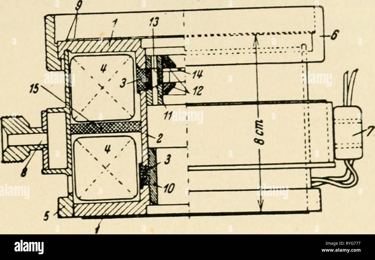 The electron microscope, its development, present performance and future possibilities electronmicrosco00gabo Year: 1948 Supermicroscopes 35 Fig. 12. Design of magnetic objective (E. Ruska, 1934) If these electrons are ultimately accelerated by v volts 11,600 the root mean square divergence is 82 — ^ 11,600 ^ J In the case of a tungsten cathode with T = 2,600°K and V = 60,000 volts this is very nearly 2.0r^. Whenever the cathode is imaged on the specimen, the di- vergence cannot be less than this value, though it can be more, as a consequence of lens errors and space charge effects. But Stock Photohttps://www.alamy.com/image-license-details/?v=1https://www.alamy.com/the-electron-microscope-its-development-present-performance-and-future-possibilities-electronmicrosco00gabo-year-1948-supermicroscopes-35-fig-12-design-of-magnetic-objective-e-ruska-1934-if-these-electrons-are-ultimately-accelerated-by-v-volts-11600-the-root-mean-square-divergence-is-82-11600-j-in-the-case-of-a-tungsten-cathode-with-t-=-2600k-and-v-=-60000-volts-this-is-very-nearly-20r-whenever-the-cathode-is-imaged-on-the-specimen-the-di-vergence-cannot-be-less-than-this-value-though-it-can-be-more-as-a-consequence-of-lens-errors-and-space-charge-effects-but-image240687419.html
RMRYG777–The electron microscope, its development, present performance and future possibilities electronmicrosco00gabo Year: 1948 Supermicroscopes 35 Fig. 12. Design of magnetic objective (E. Ruska, 1934) If these electrons are ultimately accelerated by v volts 11,600 the root mean square divergence is 82 — ^ 11,600 ^ J In the case of a tungsten cathode with T = 2,600°K and V = 60,000 volts this is very nearly 2.0r^. Whenever the cathode is imaged on the specimen, the di- vergence cannot be less than this value, though it can be more, as a consequence of lens errors and space charge effects. But
 Electron microscopy; proceedings of the Stockholm Conference, September, 1956 electronmicrosco00euro Year: 1957 Strahlnchtung 1, Permanent magnet. 2a, 2b, Disploceable polepieces of the intermediate lens. 3, Insert, at the same time fixed pole- piece at the final projector lens. 4, Disploceable polepiece of the fmal projector lens. 5, Control nut. 6, Bevel gear. Fig. 1. Cross section through a two-stage projective system operating with permanent magnets. an electron microscope objective lens a permanent magnetic einzel-lens may be used. On its electron optical properties Lenz (9) has publish Stock Photohttps://www.alamy.com/image-license-details/?v=1https://www.alamy.com/electron-microscopy-proceedings-of-the-stockholm-conference-september-1956-electronmicrosco00euro-year-1957-strahlnchtung-1-permanent-magnet-2a-2b-disploceable-polepieces-of-the-intermediate-lens-3-insert-at-the-same-time-fixed-pole-piece-at-the-final-projector-lens-4-disploceable-polepiece-of-the-fmal-projector-lens-5-control-nut-6-bevel-gear-fig-1-cross-section-through-a-two-stage-projective-system-operating-with-permanent-magnets-an-electron-microscope-objective-lens-a-permanent-magnetic-einzel-lens-may-be-used-on-its-electron-optical-properties-lenz-9-has-publish-image240664350.html
RMRYF5RA–Electron microscopy; proceedings of the Stockholm Conference, September, 1956 electronmicrosco00euro Year: 1957 Strahlnchtung 1, Permanent magnet. 2a, 2b, Disploceable polepieces of the intermediate lens. 3, Insert, at the same time fixed pole- piece at the final projector lens. 4, Disploceable polepiece of the fmal projector lens. 5, Control nut. 6, Bevel gear. Fig. 1. Cross section through a two-stage projective system operating with permanent magnets. an electron microscope objective lens a permanent magnetic einzel-lens may be used. On its electron optical properties Lenz (9) has publish
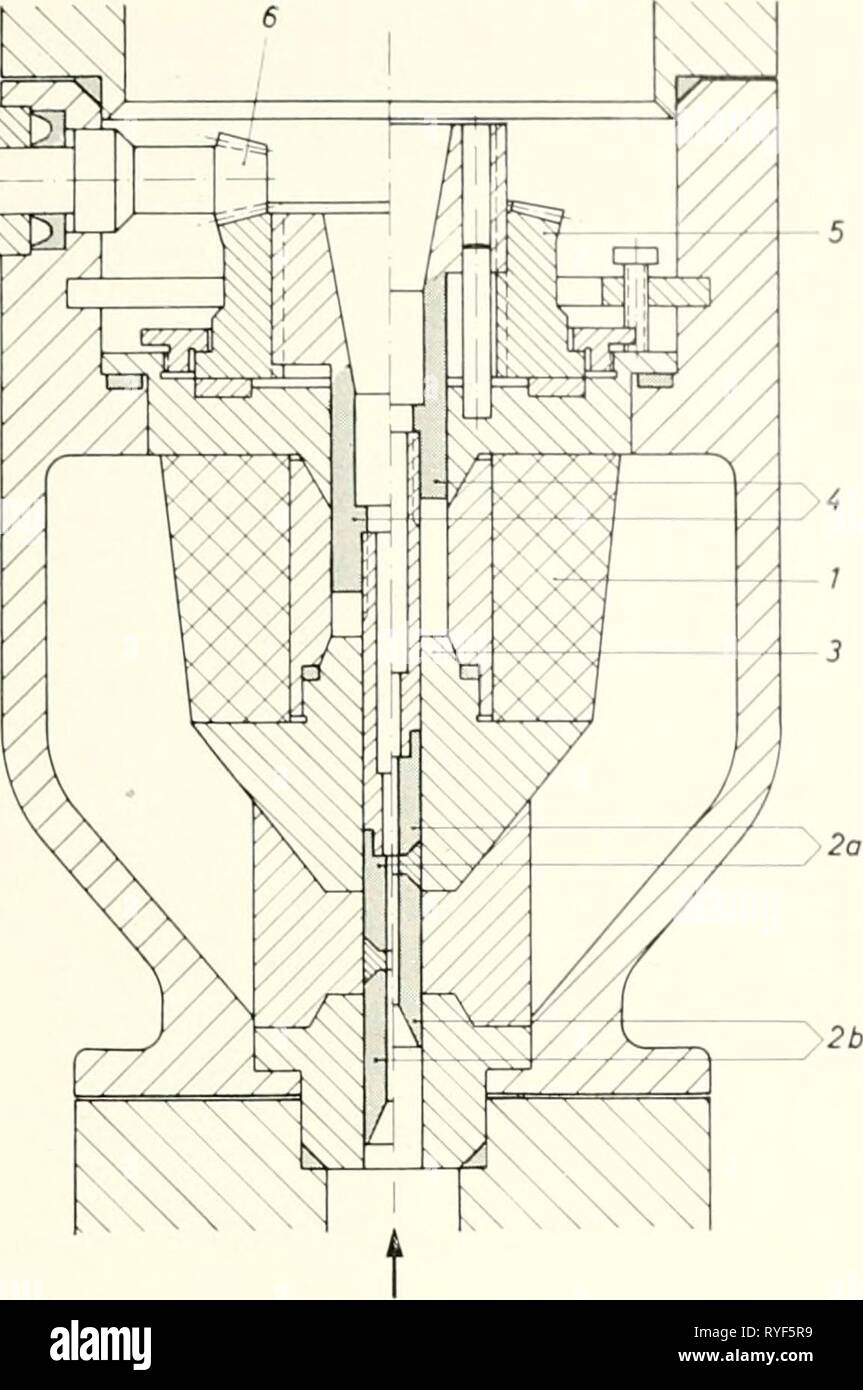 Electron microscopy; proceedings of the Stockholm Conference, September, 1956 electronmicrosco00euro Year: 1957 Imaging Elemenls with Permanent Magnets 15 ^gS ^ ^m: Strahlnchtung 1, Permanent magnet. 2a, 2b, Disploceable polepieces of the intermediate lens. 3, Insert, at the same time fixed pole- piece at the final projector lens. 4, Disploceable polepiece of the fmal projector lens. 5, Control nut. 6, Bevel gear. Fig. 1. Cross section through a two-stage projective system operating with permanent magnets. an electron microscope objective lens a permanent magnetic einzel-lens may be used. Stock Photohttps://www.alamy.com/image-license-details/?v=1https://www.alamy.com/electron-microscopy-proceedings-of-the-stockholm-conference-september-1956-electronmicrosco00euro-year-1957-imaging-elemenls-with-permanent-magnets-15-gs-m-strahlnchtung-1-permanent-magnet-2a-2b-disploceable-polepieces-of-the-intermediate-lens-3-insert-at-the-same-time-fixed-pole-piece-at-the-final-projector-lens-4-disploceable-polepiece-of-the-fmal-projector-lens-5-control-nut-6-bevel-gear-fig-1-cross-section-through-a-two-stage-projective-system-operating-with-permanent-magnets-an-electron-microscope-objective-lens-a-permanent-magnetic-einzel-lens-may-be-used-image240664349.html
RMRYF5R9–Electron microscopy; proceedings of the Stockholm Conference, September, 1956 electronmicrosco00euro Year: 1957 Imaging Elemenls with Permanent Magnets 15 ^gS ^ ^m: Strahlnchtung 1, Permanent magnet. 2a, 2b, Disploceable polepieces of the intermediate lens. 3, Insert, at the same time fixed pole- piece at the final projector lens. 4, Disploceable polepiece of the fmal projector lens. 5, Control nut. 6, Bevel gear. Fig. 1. Cross section through a two-stage projective system operating with permanent magnets. an electron microscope objective lens a permanent magnetic einzel-lens may be used.