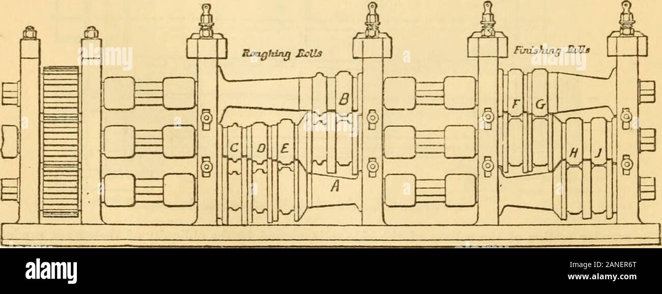
Appletons' cyclopaedia of applied mechanics: a dictionary of mechanical engineering and the mechanical arts . pair of engines with 50-in. cylinders and 4 ft. stroke, geared 2.88 to 1 to the rolls. Plates 10 ft. or10 ft. 6 in. wide can be rolled. The screws for adjusting the rolls are 9 in. in diameter and 1 in. 2475.. pitch, and they are worked by ordinary spanners (not shown) having a radius of 4 ft. and 16 arms.The feet of the housings are planed where they rest on the bed-plates, and the holes for the screw- IRON-WORKING MACHINERY. 20^ bushes bored. Holes are also cast in thehousings for th
Image details
Contributor:
The Reading Room / Alamy Stock PhotoImage ID:
2ANER6TFile size:
7.2 MB (253.7 KB Compressed download)Releases:
Model - no | Property - noDo I need a release?Dimensions:
2581 x 969 px | 21.9 x 8.2 cm | 8.6 x 3.2 inches | 300dpiMore information:
This image is a public domain image, which means either that copyright has expired in the image or the copyright holder has waived their copyright. Alamy charges you a fee for access to the high resolution copy of the image.
This image could have imperfections as it’s either historical or reportage.
Appletons' cyclopaedia of applied mechanics: a dictionary of mechanical engineering and the mechanical arts . pair of engines with 50-in. cylinders and 4 ft. stroke, geared 2.88 to 1 to the rolls. Plates 10 ft. or10 ft. 6 in. wide can be rolled. The screws for adjusting the rolls are 9 in. in diameter and 1 in. 2475.. pitch, and they are worked by ordinary spanners (not shown) having a radius of 4 ft. and 16 arms.The feet of the housings are planed where they rest on the bed-plates, and the holes for the screw- IRON-WORKING MACHINERY. 20^ bushes bored. Holes are also cast in thehousings for the balance-pillars to passthrough, and the latter are cottered intothe chocks as shown. The arrangementfor traveling the slab or plate forward intothe rolls consists of a roller 9 in. in diame-ter traversing nearly the whole length ofeach plate (front and back), as shown inthe half plan and cross-section, Figs. 2473and 2474, this roller being supported inthe middle of its length by a friction-roller.On the outer end of the bottom (main) rollis keyed a plain friction-roller 2 ft. 9 in. indiameter and 9+ in. wide, and on the endof each 9-in. roller-spindle (which passesthrough the body of the housing, and iscarried by the outer bearing) is keyed an-other roller 15 in. in diameter; betweenthe two rollers mentioned