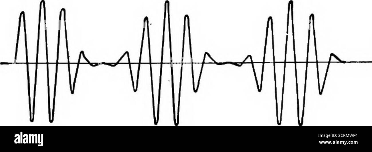
. Elements of radio telephony . FiG. 33.—Non-regenerative vacuum-tube detector set. ■denser is used in the grid circuit, the other without the gridcondenser. Referring to Fig. 33 let Ec be the voltage inducedacross the terminals of the condenser C2 due to the incomingsignal. Represented graphically it might look something Hkethe wave marked Ee in Fig. 34. If we consider the positiveparts of the waves as being above the line, and those below RECEIVING EQUIPMENT 69 negative, then when the grid voltage is positive a currentwill tend to flow in the grid circuit while no current will passwhen the g
Image details
Contributor:
Reading Room 2020 / Alamy Stock PhotoImage ID:
2CRMWP4File size:
7.1 MB (131.3 KB Compressed download)Releases:
Model - no | Property - noDo I need a release?Dimensions:
2713 x 921 px | 23 x 7.8 cm | 9 x 3.1 inches | 300dpiMore information:
This image could have imperfections as it’s either historical or reportage.
. Elements of radio telephony . FiG. 33.—Non-regenerative vacuum-tube detector set. ■denser is used in the grid circuit, the other without the gridcondenser. Referring to Fig. 33 let Ec be the voltage inducedacross the terminals of the condenser C2 due to the incomingsignal. Represented graphically it might look something Hkethe wave marked Ee in Fig. 34. If we consider the positiveparts of the waves as being above the line, and those below RECEIVING EQUIPMENT 69 negative, then when the grid voltage is positive a currentwill tend to flow in the grid circuit while no current will passwhen the grid is negative. These pulses of current passinginto the grid condenser on their passage through the gridcircuit will charge it up so that it will produce a negative CofK/enser /o/h7^e /IJL AL Al ^.^ - ^— ^^—^ ^ A/e^af^ii>e qndvottaqe. T^hphone current.. Fig. 34.—^Voltages and currents in vacuum-tube detector circuit. potential on the grid. In Fig. 34 the second line representsthe current flowing through the grid circxiit, and the thirdline the voltage to which the grid condenser is charged frominstant to instant. The high resistance across the grid con-denser prevents the condenser from becoming too highlycharged and allows the charge to leak off continuously.Referring back to Chapter III we have seen that making 70 ELEMENTS OF RADIO TELEPHONY the grid more negative produces a decrease in the plate cur-rent, thus the plate current will vary as shown in the fourthline of Fig. 34. .Since the plate current passes directlythrough the receivers, the magnetic. pull on the receiverdiaphragms will vary in accordance with the current flowingthrough them, and reproduce the desired sound. It is not always necessary to use a grid leak, as the highresistance placed across the grid is usually called. The-oretically, if no grid leak were employed