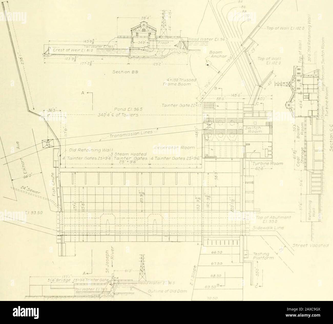
Engineering and Contracting . , or about15 ft. below headwater. Every part of thebase of the new structure was placed on un-disturbed clay in which were no seams exceptthe thin horizontal sand seams above men-tioned. Deep toothing trenches were cut intothe clay at the upstream and downstream mar-gins of the main spillway base. Downstream lained approximately the proper proportion ofsand for making a dense concrete, and forheavier mass portions of the dam and otherparts of the work was used without screeningor washing. .?11 of the thinner walls of thedam, which were built during the winter of1

Image details
Contributor:
The Reading Room / Alamy Stock PhotoImage ID:
2AXC9GXFile size:
7.2 MB (215.1 KB Compressed download)Releases:
Model - no | Property - noDo I need a release?Dimensions:
1662 x 1504 px | 28.1 x 25.5 cm | 11.1 x 10 inches | 150dpiMore information:
This image is a public domain image, which means either that copyright has expired in the image or the copyright holder has waived their copyright. Alamy charges you a fee for access to the high resolution copy of the image.
This image could have imperfections as it’s either historical or reportage.
Engineering and Contracting . , or about15 ft. below headwater. Every part of thebase of the new structure was placed on un-disturbed clay in which were no seams exceptthe thin horizontal sand seams above men-tioned. Deep toothing trenches were cut intothe clay at the upstream and downstream mar-gins of the main spillway base. Downstream lained approximately the proper proportion ofsand for making a dense concrete, and forheavier mass portions of the dam and otherparts of the work was used without screeningor washing. .?11 of the thinner walls of thedam, which were built during the winter of1911-12, were made from a mixture of brokenstone and gravel aggregate in varj-ing pro-portions so as to secure the greatest density, and with an amount of cement not exceedingIM bbl. to the cubic yard of aggregate. As soon as the weather permitted, in thespring of 1912. a washing plant was installedon the right bank of the river and within200 ft. of the end of the dam. The gravelbed lay immediately adjacent to this washini; /. Flfl. 2. General Plan and Sections of Elkhart HydroElectric Plant. hose to the chambers in the gates themselves.Similar heating devices have been installedin coimcctinu with other Tainter (jalc spill-ways designed by the Fargo Engineering Co., and all h.ivc proven successful. The foundation soil under the spillway is acompact bluish clay in which were horizontallaminations caused by l/l(i-in. or thinner tinesand scams at 1V4 or 2-in. intervals. Thesefine sand seams were exactly horizontal andso thin that under any heads existing in thecofferd.ims hut little seepage was apparent.These thin sand scams would not be noticc<lexcept for a weathered cfTcct on vertical orsloping banks, which had the appearance froma little distance of the leaves of a book. frnni the spillway base proper an apron, con-.sisting of book slabs, in general Ul.d ft. by17 ft. 4 ins. in si/c, extended for a distanceof 115 ft. The Inwcr two rows of slabs, how-ever, were made of riprap sto