Center of gravity diagram Stock Photos and Images
(21)See center of gravity diagram stock video clipsQuick filters:
Center of gravity diagram Stock Photos and Images
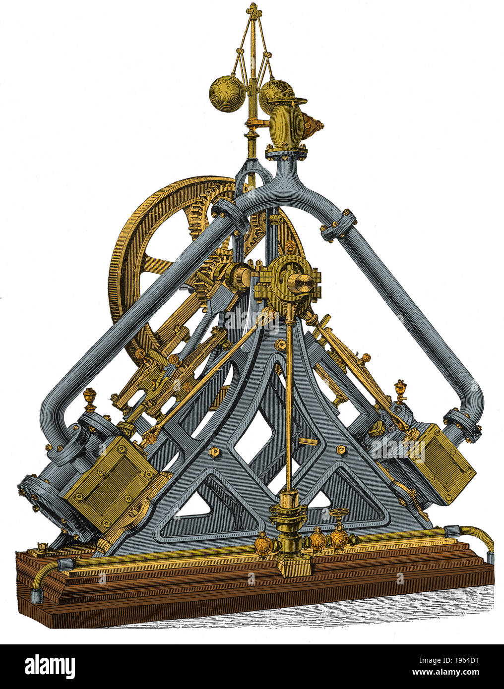 Diagonal steam engines had sloping, upward-pointing cylinders. They were usually used as a means of driving a paddle wheel shaft, while keeping a low center-of-gravity. Some used paired cylinders as Brunel's 'triangle' engine. A few were land based, most were marine. Stock Photohttps://www.alamy.com/image-license-details/?v=1https://www.alamy.com/diagonal-steam-engines-had-sloping-upward-pointing-cylinders-they-were-usually-used-as-a-means-of-driving-a-paddle-wheel-shaft-while-keeping-a-low-center-of-gravity-some-used-paired-cylinders-as-brunels-triangle-engine-a-few-were-land-based-most-were-marine-image246612292.html
RMT964DT–Diagonal steam engines had sloping, upward-pointing cylinders. They were usually used as a means of driving a paddle wheel shaft, while keeping a low center-of-gravity. Some used paired cylinders as Brunel's 'triangle' engine. A few were land based, most were marine.
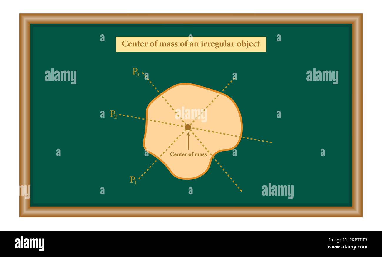 The center of mass of irregular shape object. plumb line. Physics resources for teachers and students Stock Vectorhttps://www.alamy.com/image-license-details/?v=1https://www.alamy.com/the-center-of-mass-of-irregular-shape-object-plumb-line-physics-resources-for-teachers-and-students-image558030707.html
RF2RBTDT3–The center of mass of irregular shape object. plumb line. Physics resources for teachers and students
 Manual of inspection and information for weights and measures officials . of the scale, and not exceeding such capacity, is placedso that its center of gravity lies over the points designatedby circles in diagram No. i, the error at each point shallnot exceed the tolerance allowed for the load employed.If a load equal to one-quarter of the capacity is used. WEIGHTS AND MEASURES INSPECTION 71 this shall be placed so that its center of gravity liesdirectly over the platform bearings designated by thecircles in diagram No. 2, and the errors shall not exceedthose indicated above.. Diagram No. i. 0 Stock Photohttps://www.alamy.com/image-license-details/?v=1https://www.alamy.com/manual-of-inspection-and-information-for-weights-and-measures-officials-of-the-scale-and-not-exceeding-such-capacity-is-placedso-that-its-center-of-gravity-lies-over-the-points-designatedby-circles-in-diagram-no-i-the-error-at-each-point-shallnot-exceed-the-tolerance-allowed-for-the-load-employedif-a-load-equal-to-one-quarter-of-the-capacity-is-used-weights-and-measures-inspection-71-this-shall-be-placed-so-that-its-center-of-gravity-liesdirectly-over-the-platform-bearings-designated-by-thecircles-in-diagram-no-2-and-the-errors-shall-not-exceedthose-indicated-above-diagram-no-i-0-image339120487.html
RM2AKM7HY–Manual of inspection and information for weights and measures officials . of the scale, and not exceeding such capacity, is placedso that its center of gravity lies over the points designatedby circles in diagram No. i, the error at each point shallnot exceed the tolerance allowed for the load employed.If a load equal to one-quarter of the capacity is used. WEIGHTS AND MEASURES INSPECTION 71 this shall be placed so that its center of gravity liesdirectly over the platform bearings designated by thecircles in diagram No. 2, and the errors shall not exceedthose indicated above.. Diagram No. i. 0
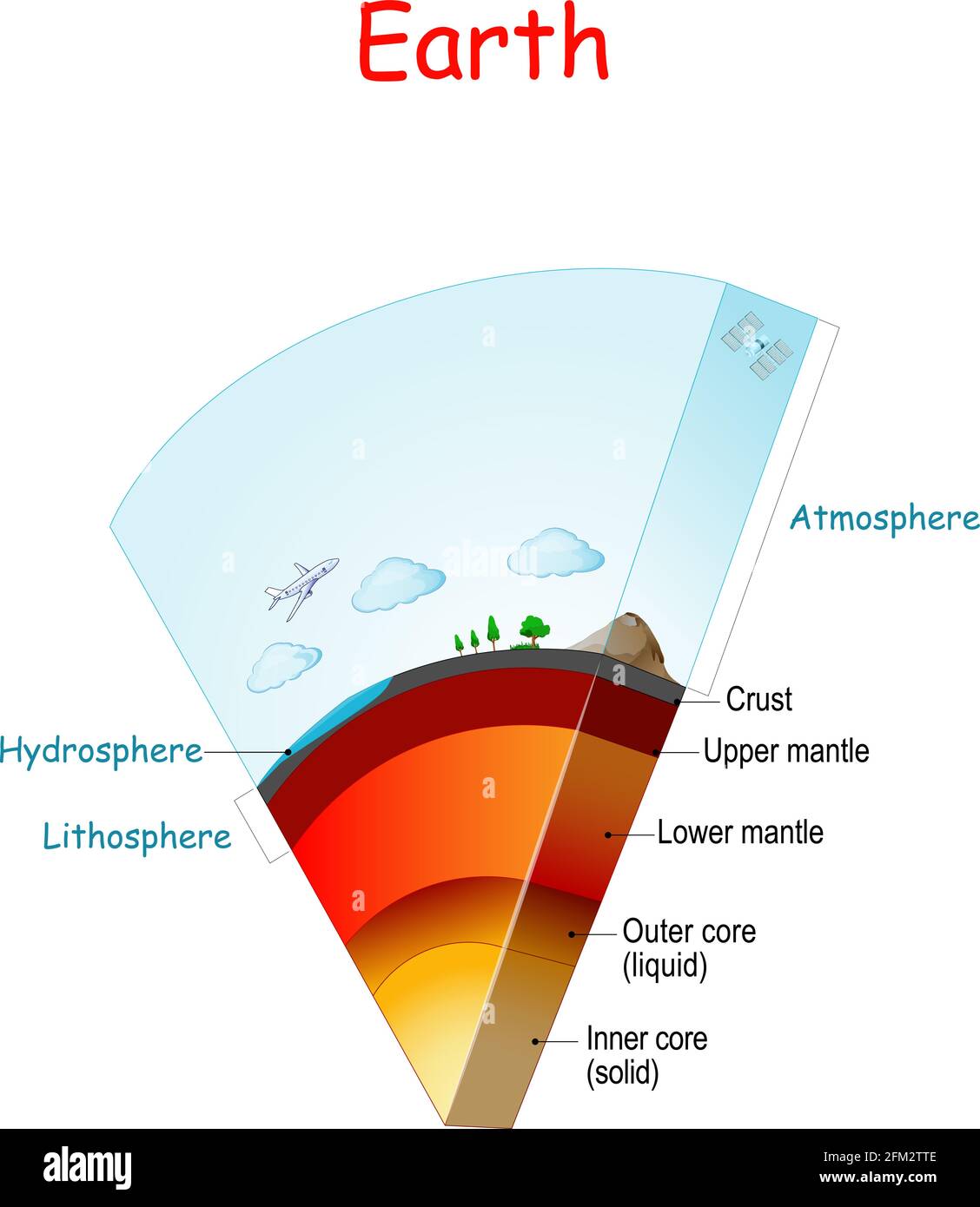 Earth structure and layers. From Lithosphere and Hydrosphere to atmosphere. Earth internal structure: core (solid, liquid), mantle (Lower, Upper) Stock Vectorhttps://www.alamy.com/image-license-details/?v=1https://www.alamy.com/earth-structure-and-layers-from-lithosphere-and-hydrosphere-to-atmosphere-earth-internal-structure-core-solid-liquid-mantle-lower-upper-image425405358.html
RF2FM2TTE–Earth structure and layers. From Lithosphere and Hydrosphere to atmosphere. Earth internal structure: core (solid, liquid), mantle (Lower, Upper)
RF2JMDAWW–Center of mass neon icon in line style. Law of physics symbol. Lever balance point. Vector illustration.
 The metacentric height is the distance between the center of gravity and the metacenter of a floating body, as of a vessel. When a vessel lists the center of buoyancy moves off centerline. The center of gravity remains on centerline. The Metacentric heigh Stock Photohttps://www.alamy.com/image-license-details/?v=1https://www.alamy.com/stock-photo-the-metacentric-height-is-the-distance-between-the-center-of-gravity-104005833.html
RMG15TE1–The metacentric height is the distance between the center of gravity and the metacenter of a floating body, as of a vessel. When a vessel lists the center of buoyancy moves off centerline. The center of gravity remains on centerline. The Metacentric heigh
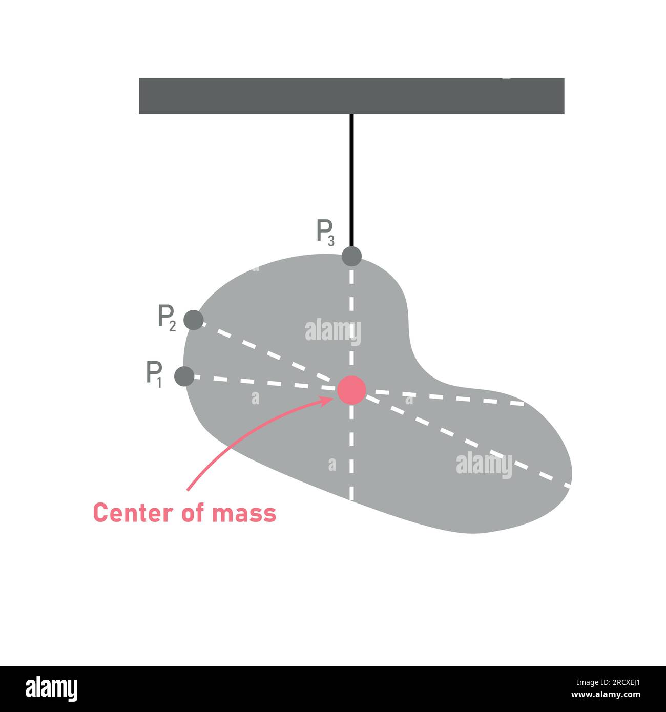 The center of mass of irregular shape object. plumb line. Vector illustration isolated on white background. Stock Vectorhttps://www.alamy.com/image-license-details/?v=1https://www.alamy.com/the-center-of-mass-of-irregular-shape-object-plumb-line-vector-illustration-isolated-on-white-background-image558689881.html
RF2RCXEJ1–The center of mass of irregular shape object. plumb line. Vector illustration isolated on white background.
 Graphical methods in reinforced concrete design . their use in practical design. Plates (EI) and (IE)and accompanying explanations give graphical solutions (26) of the formulas which will save time and labor andgive results sufficiently accurate for ^11 purposes.57. Development of Formulas. The notation adopted forbeams with single reinforcement, (see page/V ) , v.lththe addition of the following symbols, is used inthese formulas. Fig.$ is a diagram showing a numberof the symbols graphically.d = Distance from the extreme compressive fiber of the concrete to the center of gravity of the com-pre Stock Photohttps://www.alamy.com/image-license-details/?v=1https://www.alamy.com/graphical-methods-in-reinforced-concrete-design-their-use-in-practical-design-plates-ei-and-ieand-accompanying-explanations-give-graphical-solutions-26-of-the-formulas-which-will-save-time-and-labor-andgive-results-sufficiently-accurate-for-11-purposes57-development-of-formulas-the-notation-adopted-forbeams-with-single-reinforcement-see-pagev-vlththe-addition-of-the-following-symbols-is-used-inthese-formulas-fig-is-a-diagram-showing-a-numberof-the-symbols-graphicallyd-=-distance-from-the-extreme-compressive-fiber-of-the-concrete-to-the-center-of-gravity-of-the-com-pre-image338336743.html
RM2AJCFY3–Graphical methods in reinforced concrete design . their use in practical design. Plates (EI) and (IE)and accompanying explanations give graphical solutions (26) of the formulas which will save time and labor andgive results sufficiently accurate for ^11 purposes.57. Development of Formulas. The notation adopted forbeams with single reinforcement, (see page/V ) , v.lththe addition of the following symbols, is used inthese formulas. Fig.$ is a diagram showing a numberof the symbols graphically.d = Distance from the extreme compressive fiber of the concrete to the center of gravity of the com-pre
RF2JMFYY0–Center of mass icon set in flat and line style. Law of physics symbol. Lever balance point. Vector illustration.
 As steamships grew steadily in size and tonnage through the course of the 19th century, the need for low profile, low center-of-gravity engines correspondingly declined. Freed increasingly from these design constraints, engineers were able to revert to si Stock Photohttps://www.alamy.com/image-license-details/?v=1https://www.alamy.com/stock-photo-as-steamships-grew-steadily-in-size-and-tonnage-through-the-course-104005923.html
RMG15TH7–As steamships grew steadily in size and tonnage through the course of the 19th century, the need for low profile, low center-of-gravity engines correspondingly declined. Freed increasingly from these design constraints, engineers were able to revert to si
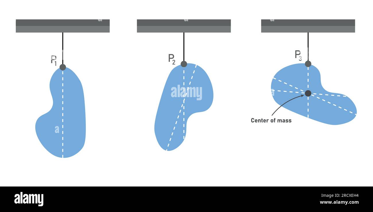 The center of mass of irregular shape object. plumb line. Vector illustration isolated on white background. Stock Vectorhttps://www.alamy.com/image-license-details/?v=1https://www.alamy.com/the-center-of-mass-of-irregular-shape-object-plumb-line-vector-illustration-isolated-on-white-background-image558689856.html
RF2RCXEH4–The center of mass of irregular shape object. plumb line. Vector illustration isolated on white background.
 . Proceedings of the annual convention . thod is used for eachcomputation. 3. Determine the average pressures pi, p^, etc., over each distance BC, CD, etc., asindicated in Fig. 3. 4. Determine the elevation of the centroid of this approximate pressure diagram. Thisis the approximate elevation of the point of application of the resultant earthpressure P. If the backfill may be considered cohesionless, the point of application of pressuremay be obtained as follows:a. Determine the center of gravity of the earth and ballast in the wedge between the plane of rupture and the vertical plane passing Stock Photohttps://www.alamy.com/image-license-details/?v=1https://www.alamy.com/proceedings-of-the-annual-convention-thod-is-used-for-eachcomputation-3-determine-the-average-pressures-pi-p-etc-over-each-distance-bc-cd-etc-asindicated-in-fig-3-4-determine-the-elevation-of-the-centroid-of-this-approximate-pressure-diagram-thisis-the-approximate-elevation-of-the-point-of-application-of-the-resultant-earthpressure-p-if-the-backfill-may-be-considered-cohesionless-the-point-of-application-of-pressuremay-be-obtained-as-followsa-determine-the-center-of-gravity-of-the-earth-and-ballast-in-the-wedge-between-the-plane-of-rupture-and-the-vertical-plane-passing-image371781716.html
RM2CGT3AC–. Proceedings of the annual convention . thod is used for eachcomputation. 3. Determine the average pressures pi, p^, etc., over each distance BC, CD, etc., asindicated in Fig. 3. 4. Determine the elevation of the centroid of this approximate pressure diagram. Thisis the approximate elevation of the point of application of the resultant earthpressure P. If the backfill may be considered cohesionless, the point of application of pressuremay be obtained as follows:a. Determine the center of gravity of the earth and ballast in the wedge between the plane of rupture and the vertical plane passing
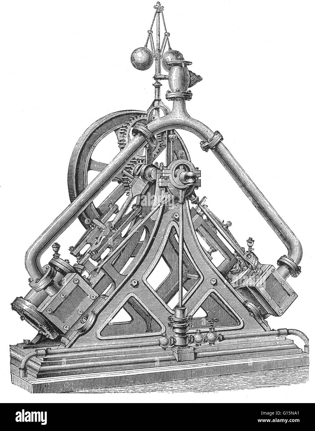 Diagonal steam engines had sloping, upward-pointing cylinders. They were usually used as a means of driving a paddle wheel shaft, while keeping a low center-of-gravity. Some used paired cylinders as Brunel's 'triangle' engine. A few were land based, most Stock Photohttps://www.alamy.com/image-license-details/?v=1https://www.alamy.com/stock-photo-diagonal-steam-engines-had-sloping-upward-pointing-cylinders-they-104003369.html
RMG15NA1–Diagonal steam engines had sloping, upward-pointing cylinders. They were usually used as a means of driving a paddle wheel shaft, while keeping a low center-of-gravity. Some used paired cylinders as Brunel's 'triangle' engine. A few were land based, most
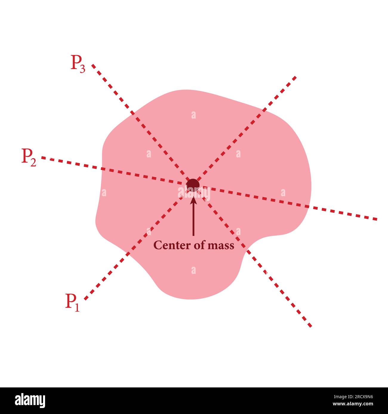 The center of mass of irregular shape object. plumb line. Vector illustration isolated on white background. Stock Vectorhttps://www.alamy.com/image-license-details/?v=1https://www.alamy.com/the-center-of-mass-of-irregular-shape-object-plumb-line-vector-illustration-isolated-on-white-background-image558686050.html
RF2RCX9N6–The center of mass of irregular shape object. plumb line. Vector illustration isolated on white background.
 . Electric railways, theoretically and practically treated . he equipmentindependently we can apply the results thus obtained to thebraking of the complete car. The Car Body. — In Fig. 135 is given a diagram of acar body, which is supported on trucks at the pointsmarked i and 2 ; the direction of motion is indicated by anarrow and the following symbols are used: W = weight of car body.h^ and h^ = retarding forces of front and rear trucks,respectively, acting at the points of sup-port./ = distance between points of support. BRAKES AND BRAKING. 213 k = distance of center of gravity of car body-a Stock Photohttps://www.alamy.com/image-license-details/?v=1https://www.alamy.com/electric-railways-theoretically-and-practically-treated-he-equipmentindependently-we-can-apply-the-results-thus-obtained-to-thebraking-of-the-complete-car-the-car-body-in-fig-135-is-given-a-diagram-of-acar-body-which-is-supported-on-trucks-at-the-pointsmarked-i-and-2-the-direction-of-motion-is-indicated-by-anarrow-and-the-following-symbols-are-used-w-=-weight-of-car-bodyh-and-h-=-retarding-forces-of-front-and-rear-trucksrespectively-acting-at-the-points-of-sup-port-=-distance-between-points-of-support-brakes-and-braking-213-k-=-distance-of-center-of-gravity-of-car-body-a-image371829019.html
RM2CGX7KR–. Electric railways, theoretically and practically treated . he equipmentindependently we can apply the results thus obtained to thebraking of the complete car. The Car Body. — In Fig. 135 is given a diagram of acar body, which is supported on trucks at the pointsmarked i and 2 ; the direction of motion is indicated by anarrow and the following symbols are used: W = weight of car body.h^ and h^ = retarding forces of front and rear trucks,respectively, acting at the points of sup-port./ = distance between points of support. BRAKES AND BRAKING. 213 k = distance of center of gravity of car body-a
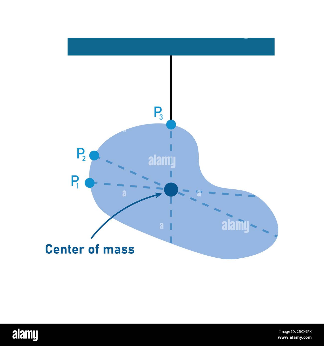 The center of mass of irregular shape object. plumb line. Vector illustration isolated on white background. Stock Vectorhttps://www.alamy.com/image-license-details/?v=1https://www.alamy.com/the-center-of-mass-of-irregular-shape-object-plumb-line-vector-illustration-isolated-on-white-background-image558686126.html
RF2RCX9RX–The center of mass of irregular shape object. plumb line. Vector illustration isolated on white background.
 . Railway mechanical engineer . rces O/, Q2. etc., which coun-teract the moments of the force P, about the center of gravity P(11 P Fig.2. (Pa) act at right angles to the arms h, c, d and e, as indi-cated in the diagram. It will also be readily seen that if Qlis the resistance offered by the bolt farthest from the centerof gravity, the resistance offered by the other bolts will besmaller in proportion to their respective distances from theorigin, or center of gravity. In other words, if Q repre-sents the resistance at unit distance, the actual resistance ofthe bolts at distances b, c, d and e Stock Photohttps://www.alamy.com/image-license-details/?v=1https://www.alamy.com/railway-mechanical-engineer-rces-o-q2-etc-which-coun-teract-the-moments-of-the-force-p-about-the-center-of-gravity-p11-p-fig2-pa-act-at-right-angles-to-the-arms-h-c-d-and-e-as-indi-cated-in-the-diagram-it-will-also-be-readily-seen-that-if-qlis-the-resistance-offered-by-the-bolt-farthest-from-the-centerof-gravity-the-resistance-offered-by-the-other-bolts-will-besmaller-in-proportion-to-their-respective-distances-from-theorigin-or-center-of-gravity-in-other-words-if-q-repre-sents-the-resistance-at-unit-distance-the-actual-resistance-ofthe-bolts-at-distances-b-c-d-and-e-image371942518.html
RM2CH3CDA–. Railway mechanical engineer . rces O/, Q2. etc., which coun-teract the moments of the force P, about the center of gravity P(11 P Fig.2. (Pa) act at right angles to the arms h, c, d and e, as indi-cated in the diagram. It will also be readily seen that if Qlis the resistance offered by the bolt farthest from the centerof gravity, the resistance offered by the other bolts will besmaller in proportion to their respective distances from theorigin, or center of gravity. In other words, if Q repre-sents the resistance at unit distance, the actual resistance ofthe bolts at distances b, c, d and e
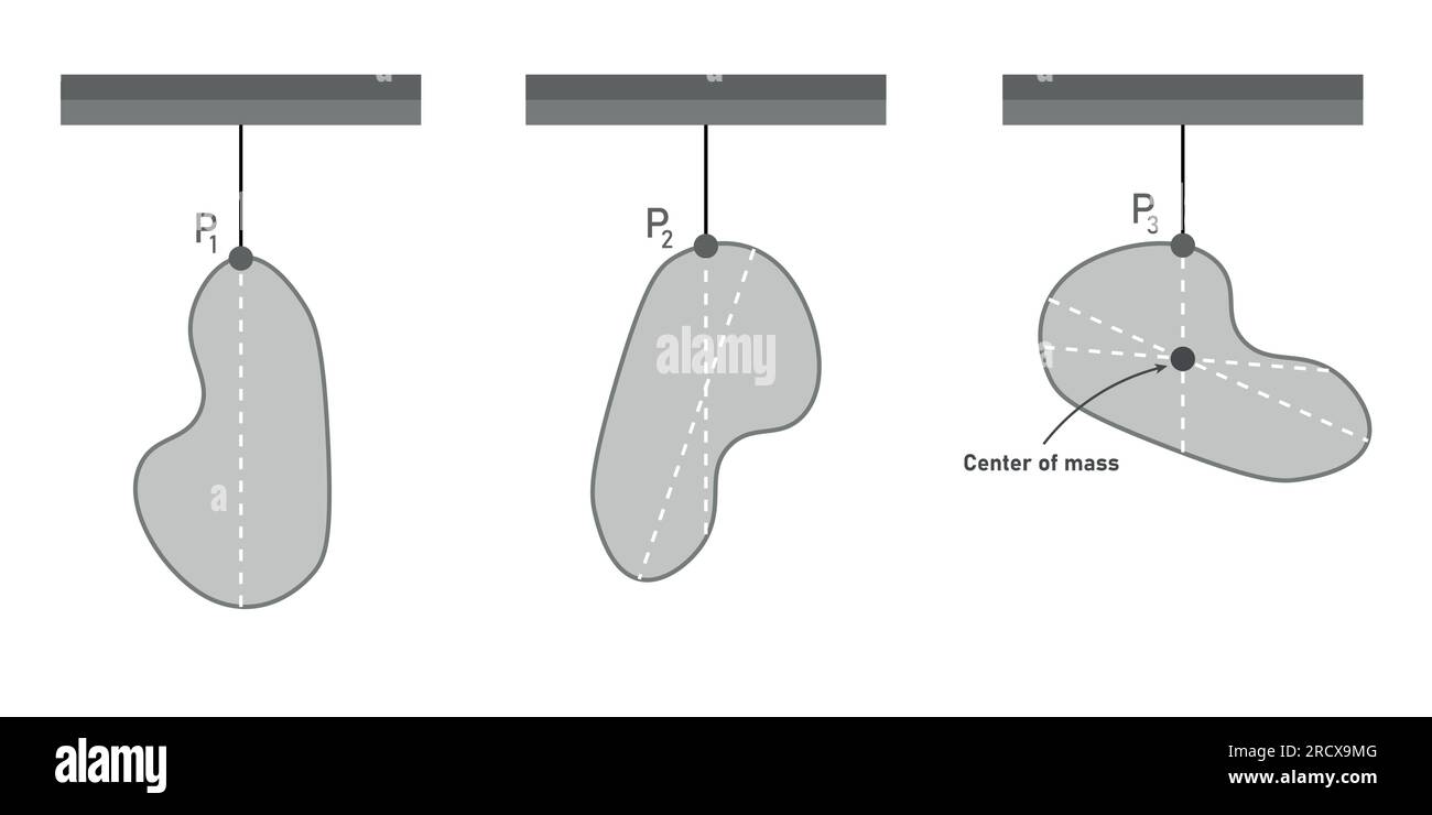 The center of mass of irregular shape object. plumb line. Vector illustration isolated on white background. Stock Vectorhttps://www.alamy.com/image-license-details/?v=1https://www.alamy.com/the-center-of-mass-of-irregular-shape-object-plumb-line-vector-illustration-isolated-on-white-background-image558686032.html
RF2RCX9MG–The center of mass of irregular shape object. plumb line. Vector illustration isolated on white background.
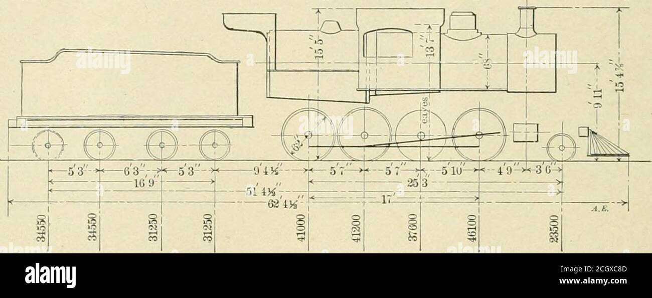 . American engineer and railroad journal . as Class H 12 in the Erie classification andthe height of the center of the boiler (68 ins. in diameter) is9 ft. 11 ins. The height to the top of the stack is 15 ft. 4Tiins. The accompanying diagram is worthy of preservation. The second in height of the center of its boiler is the 4—6—0 COMPARATIVE TESTS OF CALIFORNIA CRUDE OILS. ATCHISON, TOPEKA & SANTA FE RAILWAY. A series of tests was made recently by the Santa Fe Railwayon the crude oils found in California, to determine the rela-tive evaporative values of the light, high gravity oils foundin the Stock Photohttps://www.alamy.com/image-license-details/?v=1https://www.alamy.com/american-engineer-and-railroad-journal-as-class-h-12-in-the-erie-classification-andthe-height-of-the-center-of-the-boiler-68-ins-in-diameter-is9-ft-11-ins-the-height-to-the-top-of-the-stack-is-15-ft-4tiins-the-accompanying-diagram-is-worthy-of-preservation-the-second-in-height-of-the-center-of-its-boiler-is-the-460-comparative-tests-of-california-crude-oils-atchison-topeka-santa-fe-railway-a-series-of-tests-was-made-recently-by-the-santa-fe-railwayon-the-crude-oils-found-in-california-to-determine-the-rela-tive-evaporative-values-of-the-light-high-gravity-oils-foundin-the-image371832621.html
RM2CGXC8D–. American engineer and railroad journal . as Class H 12 in the Erie classification andthe height of the center of the boiler (68 ins. in diameter) is9 ft. 11 ins. The height to the top of the stack is 15 ft. 4Tiins. The accompanying diagram is worthy of preservation. The second in height of the center of its boiler is the 4—6—0 COMPARATIVE TESTS OF CALIFORNIA CRUDE OILS. ATCHISON, TOPEKA & SANTA FE RAILWAY. A series of tests was made recently by the Santa Fe Railwayon the crude oils found in California, to determine the rela-tive evaporative values of the light, high gravity oils foundin the
 The center of mass of irregular shape object. plumb line. Vector illustration isolated on white background. Stock Vectorhttps://www.alamy.com/image-license-details/?v=1https://www.alamy.com/the-center-of-mass-of-irregular-shape-object-plumb-line-vector-illustration-isolated-on-white-background-image558686031.html
RF2RCX9MF–The center of mass of irregular shape object. plumb line. Vector illustration isolated on white background.
 . Carnegie Institution of Washington publication. PSYCHOLOGICAL PROGRAM AND TECHNIQUE, 179 bearings so that it could revolve freely. A light aluminum arm A, fast- ened to the eccentric, extended from the axis of rotation a distance of 25 cm. This arm resting against a suitable catch C held the eccentric in a position above its center of gravity and ready to be tipped over to the left by the offset 0 carried by the wheel W. When the eccentric was lifted from the catch C, and pushed slightly past its highest position by 0, which moved from right to left, it then fell of its. Fig. 44.—Diagram of Stock Photohttps://www.alamy.com/image-license-details/?v=1https://www.alamy.com/carnegie-institution-of-washington-publication-psychological-program-and-technique-179-bearings-so-that-it-could-revolve-freely-a-light-aluminum-arm-a-fast-ened-to-the-eccentric-extended-from-the-axis-of-rotation-a-distance-of-25-cm-this-arm-resting-against-a-suitable-catch-c-held-the-eccentric-in-a-position-above-its-center-of-gravity-and-ready-to-be-tipped-over-to-the-left-by-the-offset-0-carried-by-the-wheel-w-when-the-eccentric-was-lifted-from-the-catch-c-and-pushed-slightly-past-its-highest-position-by-0-which-moved-from-right-to-left-it-then-fell-of-its-fig-44diagram-of-image233484210.html
RMRFT3DP–. Carnegie Institution of Washington publication. PSYCHOLOGICAL PROGRAM AND TECHNIQUE, 179 bearings so that it could revolve freely. A light aluminum arm A, fast- ened to the eccentric, extended from the axis of rotation a distance of 25 cm. This arm resting against a suitable catch C held the eccentric in a position above its center of gravity and ready to be tipped over to the left by the offset 0 carried by the wheel W. When the eccentric was lifted from the catch C, and pushed slightly past its highest position by 0, which moved from right to left, it then fell of its. Fig. 44.—Diagram of