Implosion underwater Stock Photos and Images
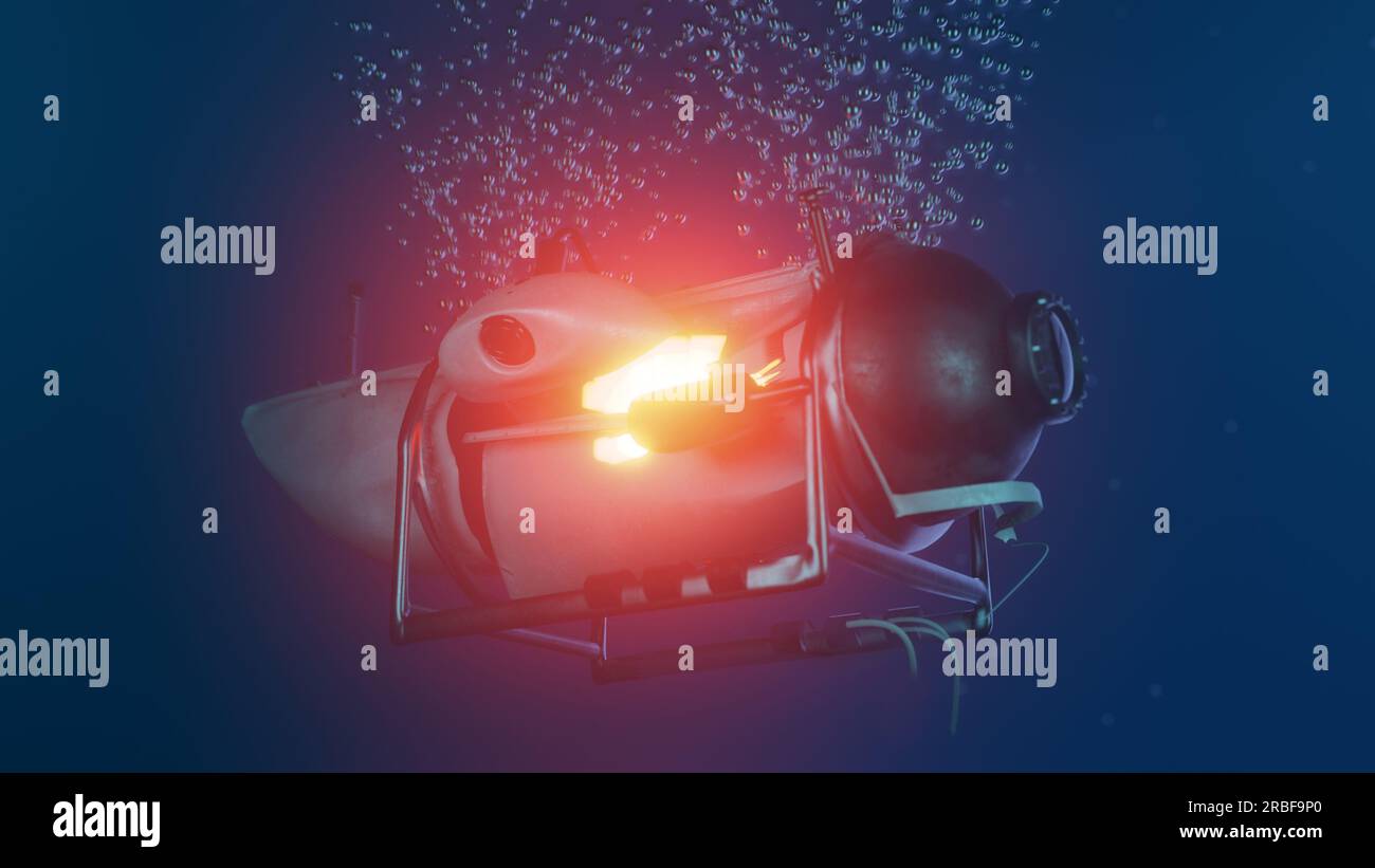 A 3D illustration of a Deep Sea Submersible Implosion Stock Photohttps://www.alamy.com/image-license-details/?v=1https://www.alamy.com/a-3d-illustration-of-a-deep-sea-submersible-implosion-image557829944.html
RF2RBF9P0–A 3D illustration of a Deep Sea Submersible Implosion
 . Design for implosion of concrete cylinder structures under hydrostatic loading. Underwater concrete construction; Hydraulic structures. u c; .s iJ. Please note that these images are extracted from scanned page images that may have been digitally enhanced for readability - coloration and appearance of these illustrations may not perfectly resemble the original work.. Haynes, H. H; Naval Construction Battalion Center (Port Hueneme, Calif. ). Civil Engineering Laboratory. Port Hueneme, Calif. : Naval Construction Battalion Center Stock Photohttps://www.alamy.com/image-license-details/?v=1https://www.alamy.com/design-for-implosion-of-concrete-cylinder-structures-under-hydrostatic-loading-underwater-concrete-construction-hydraulic-structures-u-c-s-ij-please-note-that-these-images-are-extracted-from-scanned-page-images-that-may-have-been-digitally-enhanced-for-readability-coloration-and-appearance-of-these-illustrations-may-not-perfectly-resemble-the-original-work-haynes-h-h-naval-construction-battalion-center-port-hueneme-calif-civil-engineering-laboratory-port-hueneme-calif-naval-construction-battalion-center-image215986490.html
RMPFB0Y6–. Design for implosion of concrete cylinder structures under hydrostatic loading. Underwater concrete construction; Hydraulic structures. u c; .s iJ. Please note that these images are extracted from scanned page images that may have been digitally enhanced for readability - coloration and appearance of these illustrations may not perfectly resemble the original work.. Haynes, H. H; Naval Construction Battalion Center (Port Hueneme, Calif. ). Civil Engineering Laboratory. Port Hueneme, Calif. : Naval Construction Battalion Center
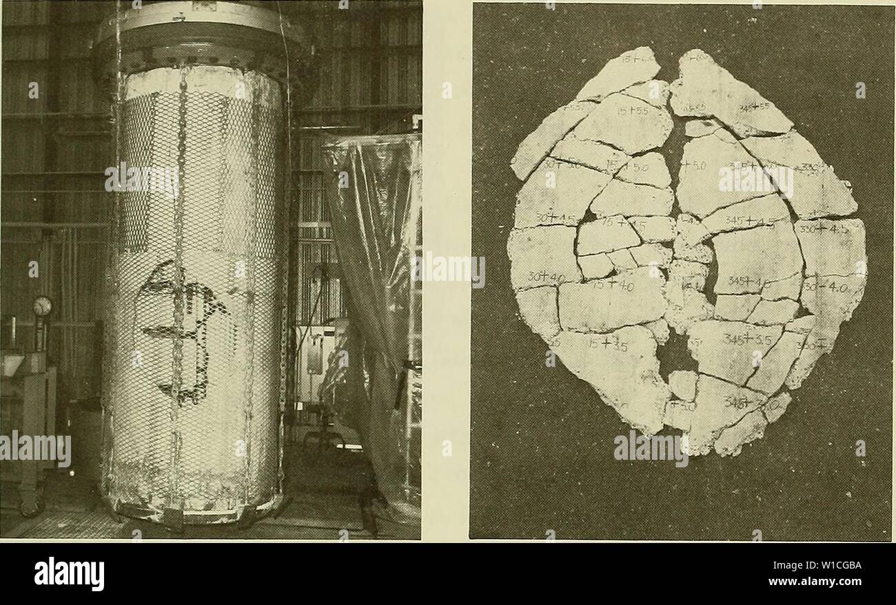 Archive image from page 64 of Design for implosion of concrete. Design for implosion of concrete cylinder structures under hydrostatic loading . designforimplosi00hayn Year: 1979 Figure B-8. Post-implosion view of specimen 1-1 (t/D = 0.024, sim- ple support). Figure B-9. Fragments of failure hole from specimen 1-1. Stock Photohttps://www.alamy.com/image-license-details/?v=1https://www.alamy.com/archive-image-from-page-64-of-design-for-implosion-of-concrete-design-for-implosion-of-concrete-cylinder-structures-under-hydrostatic-loading-designforimplosi00hayn-year-1979-figure-b-8-post-implosion-view-of-specimen-1-1-td-=-0024-sim-ple-support-figure-b-9-fragments-of-failure-hole-from-specimen-1-1-image259046462.html
RMW1CGBA–Archive image from page 64 of Design for implosion of concrete. Design for implosion of concrete cylinder structures under hydrostatic loading . designforimplosi00hayn Year: 1979 Figure B-8. Post-implosion view of specimen 1-1 (t/D = 0.024, sim- ple support). Figure B-9. Fragments of failure hole from specimen 1-1.
 . Design for implosion of concrete cylinder structures under hydrostatic loading. Underwater concrete construction; Hydraulic structures. u c; .s iJ. 65. Please note that these images are extracted from scanned page images that may have been digitally enhanced for readability - coloration and appearance of these illustrations may not perfectly resemble the original work.. Haynes, H. H; Naval Construction Battalion Center (Port Hueneme, Calif. ). Civil Engineering Laboratory. Port Hueneme, Calif. : Naval Construction Battalion Center Stock Photohttps://www.alamy.com/image-license-details/?v=1https://www.alamy.com/design-for-implosion-of-concrete-cylinder-structures-under-hydrostatic-loading-underwater-concrete-construction-hydraulic-structures-u-c-s-ij-65-please-note-that-these-images-are-extracted-from-scanned-page-images-that-may-have-been-digitally-enhanced-for-readability-coloration-and-appearance-of-these-illustrations-may-not-perfectly-resemble-the-original-work-haynes-h-h-naval-construction-battalion-center-port-hueneme-calif-civil-engineering-laboratory-port-hueneme-calif-naval-construction-battalion-center-image231661725.html
RMRCW2W1–. Design for implosion of concrete cylinder structures under hydrostatic loading. Underwater concrete construction; Hydraulic structures. u c; .s iJ. 65. Please note that these images are extracted from scanned page images that may have been digitally enhanced for readability - coloration and appearance of these illustrations may not perfectly resemble the original work.. Haynes, H. H; Naval Construction Battalion Center (Port Hueneme, Calif. ). Civil Engineering Laboratory. Port Hueneme, Calif. : Naval Construction Battalion Center
 A 3D illustration of a Deep Sea Submersible Implosion Stock Photohttps://www.alamy.com/image-license-details/?v=1https://www.alamy.com/a-3d-illustration-of-a-deep-sea-submersible-implosion-image557829939.html
RF2RBF9NR–A 3D illustration of a Deep Sea Submersible Implosion
 . Design for implosion of concrete cylinder structures under hydrostatic loading. Underwater concrete construction; Hydraulic structures. u c; .s iJ. 65. Please note that these images are extracted from scanned page images that may have been digitally enhanced for readability - coloration and appearance of these illustrations may not perfectly resemble the original work.. Haynes, H. H; Naval Construction Battalion Center (Port Hueneme, Calif. ). Civil Engineering Laboratory. Port Hueneme, Calif. : Naval Construction Battalion Center Stock Photohttps://www.alamy.com/image-license-details/?v=1https://www.alamy.com/design-for-implosion-of-concrete-cylinder-structures-under-hydrostatic-loading-underwater-concrete-construction-hydraulic-structures-u-c-s-ij-65-please-note-that-these-images-are-extracted-from-scanned-page-images-that-may-have-been-digitally-enhanced-for-readability-coloration-and-appearance-of-these-illustrations-may-not-perfectly-resemble-the-original-work-haynes-h-h-naval-construction-battalion-center-port-hueneme-calif-civil-engineering-laboratory-port-hueneme-calif-naval-construction-battalion-center-image215986486.html
RMPFB0Y2–. Design for implosion of concrete cylinder structures under hydrostatic loading. Underwater concrete construction; Hydraulic structures. u c; .s iJ. 65. Please note that these images are extracted from scanned page images that may have been digitally enhanced for readability - coloration and appearance of these illustrations may not perfectly resemble the original work.. Haynes, H. H; Naval Construction Battalion Center (Port Hueneme, Calif. ). Civil Engineering Laboratory. Port Hueneme, Calif. : Naval Construction Battalion Center
 Archive image from page 65 of Design for implosion of concrete. Design for implosion of concrete cylinder structures under hydrostatic loading . designforimplosi00hayn Year: 1979 Figure B-12. Fragments of failure hole from specimen 2-2. Figure B-13. Post-implosion view of specimen 3-1 (t/D = 0.037, sim- ple support). 60 Stock Photohttps://www.alamy.com/image-license-details/?v=1https://www.alamy.com/archive-image-from-page-65-of-design-for-implosion-of-concrete-design-for-implosion-of-concrete-cylinder-structures-under-hydrostatic-loading-designforimplosi00hayn-year-1979-figure-b-12-fragments-of-failure-hole-from-specimen-2-2-figure-b-13-post-implosion-view-of-specimen-3-1-td-=-0037-sim-ple-support-60-image259047091.html
RMW1CH5R–Archive image from page 65 of Design for implosion of concrete. Design for implosion of concrete cylinder structures under hydrostatic loading . designforimplosi00hayn Year: 1979 Figure B-12. Fragments of failure hole from specimen 2-2. Figure B-13. Post-implosion view of specimen 3-1 (t/D = 0.037, sim- ple support). 60
 . Design for implosion of concrete cylinder structures under hydrostatic loading. Underwater concrete construction; Hydraulic structures. u c; .s iJ. Please note that these images are extracted from scanned page images that may have been digitally enhanced for readability - coloration and appearance of these illustrations may not perfectly resemble the original work.. Haynes, H. H; Naval Construction Battalion Center (Port Hueneme, Calif. ). Civil Engineering Laboratory. Port Hueneme, Calif. : Naval Construction Battalion Center Stock Photohttps://www.alamy.com/image-license-details/?v=1https://www.alamy.com/design-for-implosion-of-concrete-cylinder-structures-under-hydrostatic-loading-underwater-concrete-construction-hydraulic-structures-u-c-s-ij-please-note-that-these-images-are-extracted-from-scanned-page-images-that-may-have-been-digitally-enhanced-for-readability-coloration-and-appearance-of-these-illustrations-may-not-perfectly-resemble-the-original-work-haynes-h-h-naval-construction-battalion-center-port-hueneme-calif-civil-engineering-laboratory-port-hueneme-calif-naval-construction-battalion-center-image231661733.html
RMRCW2W9–. Design for implosion of concrete cylinder structures under hydrostatic loading. Underwater concrete construction; Hydraulic structures. u c; .s iJ. Please note that these images are extracted from scanned page images that may have been digitally enhanced for readability - coloration and appearance of these illustrations may not perfectly resemble the original work.. Haynes, H. H; Naval Construction Battalion Center (Port Hueneme, Calif. ). Civil Engineering Laboratory. Port Hueneme, Calif. : Naval Construction Battalion Center
 . Design for implosion of concrete cylinder structures under hydrostatic loading. Underwater concrete construction; Hydraulic structures. / ( ^ neoprene 1 $$$$^ ^ —-K{— J »- H : "i^^^^^ r c - - ^ ) ^ m ^' v^vv^:^ / L / 1 ^ ^vvvvvvvvv^ ^ n 44. Please note that these images are extracted from scanned page images that may have been digitally enhanced for readability - coloration and appearance of these illustrations may not perfectly resemble the original work.. Haynes, H. H; Naval Construction Battalion Center (Port Stock Photohttps://www.alamy.com/image-license-details/?v=1https://www.alamy.com/design-for-implosion-of-concrete-cylinder-structures-under-hydrostatic-loading-underwater-concrete-construction-hydraulic-structures-neoprene-1-k-j-h-quoti-r-c-m-vvv-l-1-vvvvvvvvv-n-44-please-note-that-these-images-are-extracted-from-scanned-page-images-that-may-have-been-digitally-enhanced-for-readability-coloration-and-appearance-of-these-illustrations-may-not-perfectly-resemble-the-original-work-haynes-h-h-naval-construction-battalion-center-port-image215986544.html
RMPFB114–. Design for implosion of concrete cylinder structures under hydrostatic loading. Underwater concrete construction; Hydraulic structures. / ( ^ neoprene 1 $$$$^ ^ —-K{— J »- H : "i^^^^^ r c - - ^ ) ^ m ^' v^vv^:^ / L / 1 ^ ^vvvvvvvvv^ ^ n 44. Please note that these images are extracted from scanned page images that may have been digitally enhanced for readability - coloration and appearance of these illustrations may not perfectly resemble the original work.. Haynes, H. H; Naval Construction Battalion Center (Port
 Archive image from page 80 of Design for implosion of concrete. Design for implosion of concrete cylinder structures under hydrostatic loading . designforimplosi00hayn Year: 1979 Wall thickness = U,,„ -0.08 in. Figure B-26. Idealized initial out-of-round shape for cylinders with n = 3. AR„ = -0.10 in. Wall Thickness = ta„a -0-08 in. Figure B-27. Idealized initial out-of-round shape for cylinders with n = 2. 75 Stock Photohttps://www.alamy.com/image-license-details/?v=1https://www.alamy.com/archive-image-from-page-80-of-design-for-implosion-of-concrete-design-for-implosion-of-concrete-cylinder-structures-under-hydrostatic-loading-designforimplosi00hayn-year-1979-wall-thickness-=-u-008-in-figure-b-26-idealized-initial-out-of-round-shape-for-cylinders-with-n-=-3-ar-=-010-in-wall-thickness-=-taa-0-08-in-figure-b-27-idealized-initial-out-of-round-shape-for-cylinders-with-n-=-2-75-image259055166.html
RMW1CYE6–Archive image from page 80 of Design for implosion of concrete. Design for implosion of concrete cylinder structures under hydrostatic loading . designforimplosi00hayn Year: 1979 Wall thickness = U,,„ -0.08 in. Figure B-26. Idealized initial out-of-round shape for cylinders with n = 3. AR„ = -0.10 in. Wall Thickness = ta„a -0-08 in. Figure B-27. Idealized initial out-of-round shape for cylinders with n = 2. 75
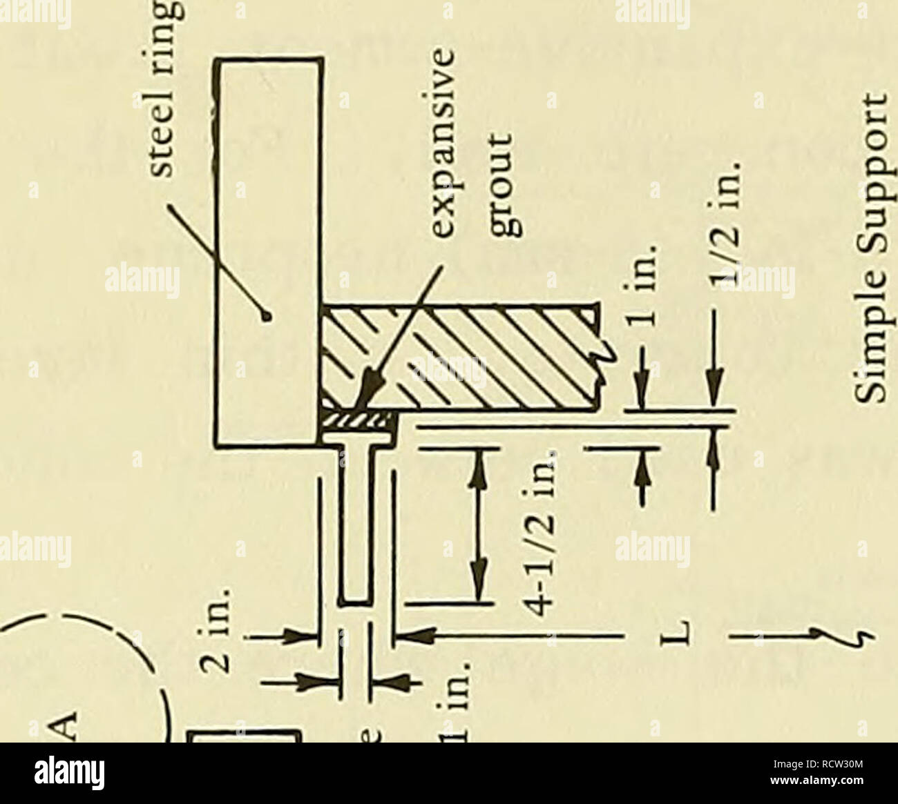 . Design for implosion of concrete cylinder structures under hydrostatic loading. Underwater concrete construction; Hydraulic structures. / ( ^ neoprene 1 $$$$^ ^ —-K{— J »- H : "i^^^^^ r c - - ^ ) ^ m ^' v^vv^:^ / L / 1 ^ ^vvvvvvvvv^ ^ n 44. Please note that these images are extracted from scanned page images that may have been digitally enhanced for readability - coloration and appearance of these illustrations may not perfectly resemble the original work.. Haynes, H. H; Naval Construction Battalion Center (Port Stock Photohttps://www.alamy.com/image-license-details/?v=1https://www.alamy.com/design-for-implosion-of-concrete-cylinder-structures-under-hydrostatic-loading-underwater-concrete-construction-hydraulic-structures-neoprene-1-k-j-h-quoti-r-c-m-vvv-l-1-vvvvvvvvv-n-44-please-note-that-these-images-are-extracted-from-scanned-page-images-that-may-have-been-digitally-enhanced-for-readability-coloration-and-appearance-of-these-illustrations-may-not-perfectly-resemble-the-original-work-haynes-h-h-naval-construction-battalion-center-port-image231661828.html
RMRCW30M–. Design for implosion of concrete cylinder structures under hydrostatic loading. Underwater concrete construction; Hydraulic structures. / ( ^ neoprene 1 $$$$^ ^ —-K{— J »- H : "i^^^^^ r c - - ^ ) ^ m ^' v^vv^:^ / L / 1 ^ ^vvvvvvvvv^ ^ n 44. Please note that these images are extracted from scanned page images that may have been digitally enhanced for readability - coloration and appearance of these illustrations may not perfectly resemble the original work.. Haynes, H. H; Naval Construction Battalion Center (Port
 . Design for implosion of concrete cylinder structures under hydrostatic loading. Underwater concrete construction; Hydraulic structures. Figure A-1. SEACON structure prepared for ocean test to implosion. epoxv 2" clear adhesive --| |— ,1" cover epoxy adhesive. Please note that these images are extracted from scanned page images that may have been digitally enhanced for readability - coloration and appearance of these illustrations may not perfectly resemble the original work.. Haynes, H. H; Naval Construction Battalion Center (Port Hueneme, Calif. ). Civil Engineering Laboratory. Po Stock Photohttps://www.alamy.com/image-license-details/?v=1https://www.alamy.com/design-for-implosion-of-concrete-cylinder-structures-under-hydrostatic-loading-underwater-concrete-construction-hydraulic-structures-figure-a-1-seacon-structure-prepared-for-ocean-test-to-implosion-epoxv-2quot-clear-adhesive-1quot-cover-epoxy-adhesive-please-note-that-these-images-are-extracted-from-scanned-page-images-that-may-have-been-digitally-enhanced-for-readability-coloration-and-appearance-of-these-illustrations-may-not-perfectly-resemble-the-original-work-haynes-h-h-naval-construction-battalion-center-port-hueneme-calif-civil-engineering-laboratory-po-image215986572.html
RMPFB124–. Design for implosion of concrete cylinder structures under hydrostatic loading. Underwater concrete construction; Hydraulic structures. Figure A-1. SEACON structure prepared for ocean test to implosion. epoxv 2" clear adhesive --| |— ,1" cover epoxy adhesive. Please note that these images are extracted from scanned page images that may have been digitally enhanced for readability - coloration and appearance of these illustrations may not perfectly resemble the original work.. Haynes, H. H; Naval Construction Battalion Center (Port Hueneme, Calif. ). Civil Engineering Laboratory. Po
 Archive image from page 69 of Design for implosion of concrete. Design for implosion of concrete cylinder structures under hydrostatic loading . designforimplosi00hayn Year: 1979 initial shape initial membrane circle deflected shape deflected membrane circle w = displacement from initial to deflected shape Wj = displacement from mem- brane behavior Wu = displacement from bending w-j. = total displacement ARj = initial deviation in inside radius Figure B-17. Definition of displacement terms. When a deflected shape was plotted the reference point was the location of the center shaft that hel Stock Photohttps://www.alamy.com/image-license-details/?v=1https://www.alamy.com/archive-image-from-page-69-of-design-for-implosion-of-concrete-design-for-implosion-of-concrete-cylinder-structures-under-hydrostatic-loading-designforimplosi00hayn-year-1979-initial-shape-initial-membrane-circle-deflected-shape-deflected-membrane-circle-w-=-displacement-from-initial-to-deflected-shape-wj-=-displacement-from-mem-brane-behavior-wu-=-displacement-from-bending-w-j-=-total-displacement-arj-=-initial-deviation-in-inside-radius-figure-b-17-definition-of-displacement-terms-when-a-deflected-shape-was-plotted-the-reference-point-was-the-location-of-the-center-shaft-that-hel-image259049549.html
RMW1CM9H–Archive image from page 69 of Design for implosion of concrete. Design for implosion of concrete cylinder structures under hydrostatic loading . designforimplosi00hayn Year: 1979 initial shape initial membrane circle deflected shape deflected membrane circle w = displacement from initial to deflected shape Wj = displacement from mem- brane behavior Wu = displacement from bending w-j. = total displacement ARj = initial deviation in inside radius Figure B-17. Definition of displacement terms. When a deflected shape was plotted the reference point was the location of the center shaft that hel
 . Design for implosion of concrete cylinder structures under hydrostatic loading. Underwater concrete construction; Hydraulic structures. Figure A-1. SEACON structure prepared for ocean test to implosion. epoxv 2" clear adhesive --| |— ,1" cover epoxy adhesive. Please note that these images are extracted from scanned page images that may have been digitally enhanced for readability - coloration and appearance of these illustrations may not perfectly resemble the original work.. Haynes, H. H; Naval Construction Battalion Center (Port Hueneme, Calif. ). Civil Engineering Laboratory. Po Stock Photohttps://www.alamy.com/image-license-details/?v=1https://www.alamy.com/design-for-implosion-of-concrete-cylinder-structures-under-hydrostatic-loading-underwater-concrete-construction-hydraulic-structures-figure-a-1-seacon-structure-prepared-for-ocean-test-to-implosion-epoxv-2quot-clear-adhesive-1quot-cover-epoxy-adhesive-please-note-that-these-images-are-extracted-from-scanned-page-images-that-may-have-been-digitally-enhanced-for-readability-coloration-and-appearance-of-these-illustrations-may-not-perfectly-resemble-the-original-work-haynes-h-h-naval-construction-battalion-center-port-hueneme-calif-civil-engineering-laboratory-po-image231661869.html
RMRCW325–. Design for implosion of concrete cylinder structures under hydrostatic loading. Underwater concrete construction; Hydraulic structures. Figure A-1. SEACON structure prepared for ocean test to implosion. epoxv 2" clear adhesive --| |— ,1" cover epoxy adhesive. Please note that these images are extracted from scanned page images that may have been digitally enhanced for readability - coloration and appearance of these illustrations may not perfectly resemble the original work.. Haynes, H. H; Naval Construction Battalion Center (Port Hueneme, Calif. ). Civil Engineering Laboratory. Po
 . Design for implosion of concrete cylinder structures under hydrostatic loading. Underwater concrete construction; Hydraulic structures. Figure A-1. SEACON structure prepared for ocean test to implosion. epoxv 2" clear adhesive --| |— ,1" cover epoxy adhesive. axial and hoop reinforcement 0.7% by area 20'-0" overall length Figure A-2. Details of SEACON structure. 30. Please note that these images are extracted from scanned page images that may have been digitally enhanced for readability - coloration and appearance of these illustrations may not perfectly resemble the original Stock Photohttps://www.alamy.com/image-license-details/?v=1https://www.alamy.com/design-for-implosion-of-concrete-cylinder-structures-under-hydrostatic-loading-underwater-concrete-construction-hydraulic-structures-figure-a-1-seacon-structure-prepared-for-ocean-test-to-implosion-epoxv-2quot-clear-adhesive-1quot-cover-epoxy-adhesive-axial-and-hoop-reinforcement-07-by-area-20-0quot-overall-length-figure-a-2-details-of-seacon-structure-30-please-note-that-these-images-are-extracted-from-scanned-page-images-that-may-have-been-digitally-enhanced-for-readability-coloration-and-appearance-of-these-illustrations-may-not-perfectly-resemble-the-original-image215986568.html
RMPFB120–. Design for implosion of concrete cylinder structures under hydrostatic loading. Underwater concrete construction; Hydraulic structures. Figure A-1. SEACON structure prepared for ocean test to implosion. epoxv 2" clear adhesive --| |— ,1" cover epoxy adhesive. axial and hoop reinforcement 0.7% by area 20'-0" overall length Figure A-2. Details of SEACON structure. 30. Please note that these images are extracted from scanned page images that may have been digitally enhanced for readability - coloration and appearance of these illustrations may not perfectly resemble the original
 Archive image from page 65 of Design for implosion of concrete. Design for implosion of concrete cylinder structures under hydrostatic loading . designforimplosi00hayn Year: 1979 material was not a good substitu- tion. Figure B-16 shows that specimen 5-2 had a very local failure at the top edge which was a bearing-type failure. Boundary behavior is quanti- fied in Table B-4. For conveni- ence, a nondimensional value, 4), was selected to express boundary behavior as the ratio of radial displacement at the end supports to the radial displacement at midlength of the specimen. A rigid support wou Stock Photohttps://www.alamy.com/image-license-details/?v=1https://www.alamy.com/archive-image-from-page-65-of-design-for-implosion-of-concrete-design-for-implosion-of-concrete-cylinder-structures-under-hydrostatic-loading-designforimplosi00hayn-year-1979-material-was-not-a-good-substitu-tion-figure-b-16-shows-that-specimen-5-2-had-a-very-local-failure-at-the-top-edge-which-was-a-bearing-type-failure-boundary-behavior-is-quanti-fied-in-table-b-4-for-conveni-ence-a-nondimensional-value-4-was-selected-to-express-boundary-behavior-as-the-ratio-of-radial-displacement-at-the-end-supports-to-the-radial-displacement-at-midlength-of-the-specimen-a-rigid-support-wou-image259047100.html
RMW1CH64–Archive image from page 65 of Design for implosion of concrete. Design for implosion of concrete cylinder structures under hydrostatic loading . designforimplosi00hayn Year: 1979 material was not a good substitu- tion. Figure B-16 shows that specimen 5-2 had a very local failure at the top edge which was a bearing-type failure. Boundary behavior is quanti- fied in Table B-4. For conveni- ence, a nondimensional value, 4), was selected to express boundary behavior as the ratio of radial displacement at the end supports to the radial displacement at midlength of the specimen. A rigid support wou
 . Design for implosion of concrete cylinder structures under hydrostatic loading. Underwater concrete construction; Hydraulic structures. Figure A-1. SEACON structure prepared for ocean test to implosion. epoxv 2" clear adhesive --| |— ,1" cover epoxy adhesive. axial and hoop reinforcement 0.7% by area 20'-0" overall length Figure A-2. Details of SEACON structure. 30. Please note that these images are extracted from scanned page images that may have been digitally enhanced for readability - coloration and appearance of these illustrations may not perfectly resemble the original Stock Photohttps://www.alamy.com/image-license-details/?v=1https://www.alamy.com/design-for-implosion-of-concrete-cylinder-structures-under-hydrostatic-loading-underwater-concrete-construction-hydraulic-structures-figure-a-1-seacon-structure-prepared-for-ocean-test-to-implosion-epoxv-2quot-clear-adhesive-1quot-cover-epoxy-adhesive-axial-and-hoop-reinforcement-07-by-area-20-0quot-overall-length-figure-a-2-details-of-seacon-structure-30-please-note-that-these-images-are-extracted-from-scanned-page-images-that-may-have-been-digitally-enhanced-for-readability-coloration-and-appearance-of-these-illustrations-may-not-perfectly-resemble-the-original-image231661858.html
RMRCW31P–. Design for implosion of concrete cylinder structures under hydrostatic loading. Underwater concrete construction; Hydraulic structures. Figure A-1. SEACON structure prepared for ocean test to implosion. epoxv 2" clear adhesive --| |— ,1" cover epoxy adhesive. axial and hoop reinforcement 0.7% by area 20'-0" overall length Figure A-2. Details of SEACON structure. 30. Please note that these images are extracted from scanned page images that may have been digitally enhanced for readability - coloration and appearance of these illustrations may not perfectly resemble the original
 . Design for implosion of concrete cylinder structures under hydrostatic loading. Underwater concrete construction; Hydraulic structures. initial shape. initial membrane circle deflected shape deflected membrane circle w = displacement from initial to deflected shape Wj^ = displacement from mem- brane behavior Wu = displacement from bending w-j. = total displacement ARj = initial deviation in inside radius Figure B-17. Definition of displacement terms. When a deflected shape was plotted the reference point was the location of the center shaft that held the potentiometer; however, this location Stock Photohttps://www.alamy.com/image-license-details/?v=1https://www.alamy.com/design-for-implosion-of-concrete-cylinder-structures-under-hydrostatic-loading-underwater-concrete-construction-hydraulic-structures-initial-shape-initial-membrane-circle-deflected-shape-deflected-membrane-circle-w-=-displacement-from-initial-to-deflected-shape-wj-=-displacement-from-mem-brane-behavior-wu-=-displacement-from-bending-w-j-=-total-displacement-arj-=-initial-deviation-in-inside-radius-figure-b-17-definition-of-displacement-terms-when-a-deflected-shape-was-plotted-the-reference-point-was-the-location-of-the-center-shaft-that-held-the-potentiometer-however-this-location-image215986495.html
RMPFB0YB–. Design for implosion of concrete cylinder structures under hydrostatic loading. Underwater concrete construction; Hydraulic structures. initial shape. initial membrane circle deflected shape deflected membrane circle w = displacement from initial to deflected shape Wj^ = displacement from mem- brane behavior Wu = displacement from bending w-j. = total displacement ARj = initial deviation in inside radius Figure B-17. Definition of displacement terms. When a deflected shape was plotted the reference point was the location of the center shaft that held the potentiometer; however, this location
 Archive image from page 16 of Design for implosion of concrete. Design for implosion of concrete cylinder structures under hydrostatic loading . designforimplosi00hayn Year: 1979 The empirical expression has the rational basis of being derived from the parabolic relationship for tangent modulus as follows: 2 f , where E = tangent modulus £ = ultimate strain (experimental average was 0.0025) and the fitted condition of a = 0.56 f when E. = E. c it ACI E: = ST.OOOs/fT 1 â '⢠c 0 6xl2-in. control cylinder 7,000 8,000 Compressive Strength, f (psi) 9,000 Figure 4. Relationship between E: and Stock Photohttps://www.alamy.com/image-license-details/?v=1https://www.alamy.com/archive-image-from-page-16-of-design-for-implosion-of-concrete-design-for-implosion-of-concrete-cylinder-structures-under-hydrostatic-loading-designforimplosi00hayn-year-1979-the-empirical-expression-has-the-rational-basis-of-being-derived-from-the-parabolic-relationship-for-tangent-modulus-as-follows-2-f-where-e-=-tangent-modulus-=-ultimate-strain-experimental-average-was-00025-and-the-fitted-condition-of-a-=-056-f-when-e-=-e-c-it-aci-e-=-stooosft-1-c-0-6xl2-in-control-cylinder-7000-8000-compressive-strength-f-psi-9000-figure-4-relationship-between-e-and-image258872241.html
RMW14J55–Archive image from page 16 of Design for implosion of concrete. Design for implosion of concrete cylinder structures under hydrostatic loading . designforimplosi00hayn Year: 1979 The empirical expression has the rational basis of being derived from the parabolic relationship for tangent modulus as follows: 2 f , where E = tangent modulus £ = ultimate strain (experimental average was 0.0025) and the fitted condition of a = 0.56 f when E. = E. c it ACI E: = ST.OOOs/fT 1 â '⢠c 0 6xl2-in. control cylinder 7,000 8,000 Compressive Strength, f (psi) 9,000 Figure 4. Relationship between E: and
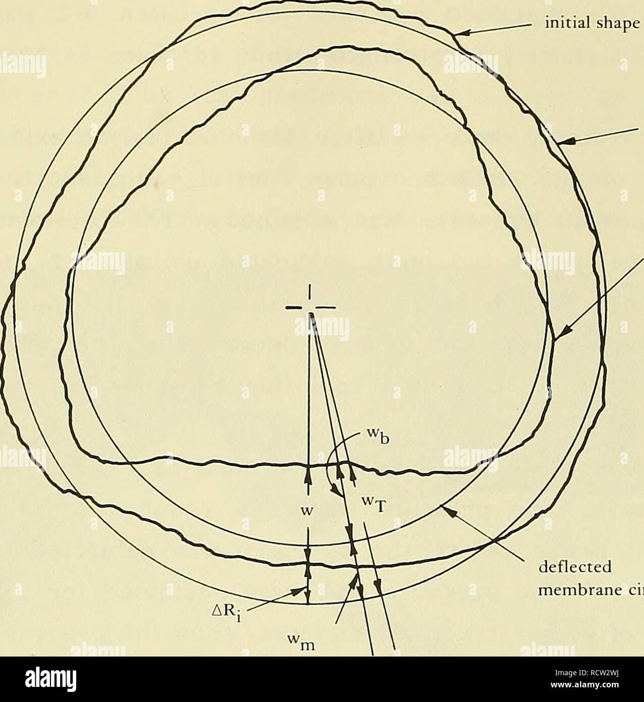 . Design for implosion of concrete cylinder structures under hydrostatic loading. Underwater concrete construction; Hydraulic structures. initial shape. initial membrane circle deflected shape deflected membrane circle w = displacement from initial to deflected shape Wj^ = displacement from mem- brane behavior Wu = displacement from bending w-j. = total displacement ARj = initial deviation in inside radius Figure B-17. Definition of displacement terms. When a deflected shape was plotted the reference point was the location of the center shaft that held the potentiometer; however, this location Stock Photohttps://www.alamy.com/image-license-details/?v=1https://www.alamy.com/design-for-implosion-of-concrete-cylinder-structures-under-hydrostatic-loading-underwater-concrete-construction-hydraulic-structures-initial-shape-initial-membrane-circle-deflected-shape-deflected-membrane-circle-w-=-displacement-from-initial-to-deflected-shape-wj-=-displacement-from-mem-brane-behavior-wu-=-displacement-from-bending-w-j-=-total-displacement-arj-=-initial-deviation-in-inside-radius-figure-b-17-definition-of-displacement-terms-when-a-deflected-shape-was-plotted-the-reference-point-was-the-location-of-the-center-shaft-that-held-the-potentiometer-however-this-location-image231661742.html
RMRCW2WJ–. Design for implosion of concrete cylinder structures under hydrostatic loading. Underwater concrete construction; Hydraulic structures. initial shape. initial membrane circle deflected shape deflected membrane circle w = displacement from initial to deflected shape Wj^ = displacement from mem- brane behavior Wu = displacement from bending w-j. = total displacement ARj = initial deviation in inside radius Figure B-17. Definition of displacement terms. When a deflected shape was plotted the reference point was the location of the center shaft that held the potentiometer; however, this location
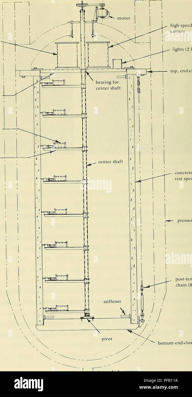 . Design for implosion of concrete cylinder structures under hydrostatic loading. Underwater concrete construction; Hydraulic structures. four-arm spider potentiometer. lights (2 locations) top, end-closure ring concrete cylinder test specimen pressure vessel post-tensionmg chain (8 equally spaced) bottom end-closure —* high-pressure | J inlet and drain Figure B-3. Cross section of specimen, showing test setup. 42. Please note that these images are extracted from scanned page images that may have been digitally enhanced for readability - coloration and appearance of these illustrations ma Stock Photohttps://www.alamy.com/image-license-details/?v=1https://www.alamy.com/design-for-implosion-of-concrete-cylinder-structures-under-hydrostatic-loading-underwater-concrete-construction-hydraulic-structures-four-arm-spider-potentiometer-lights-2-locations-top-end-closure-ring-concrete-cylinder-test-specimen-pressure-vessel-post-tensionmg-chain-8-equally-spaced-bottom-end-closure-high-pressure-j-inlet-and-drain-figure-b-3-cross-section-of-specimen-showing-test-setup-42-please-note-that-these-images-are-extracted-from-scanned-page-images-that-may-have-been-digitally-enhanced-for-readability-coloration-and-appearance-of-these-illustrations-ma-image215986550.html
RMPFB11A–. Design for implosion of concrete cylinder structures under hydrostatic loading. Underwater concrete construction; Hydraulic structures. four-arm spider potentiometer. lights (2 locations) top, end-closure ring concrete cylinder test specimen pressure vessel post-tensionmg chain (8 equally spaced) bottom end-closure —* high-pressure | J inlet and drain Figure B-3. Cross section of specimen, showing test setup. 42. Please note that these images are extracted from scanned page images that may have been digitally enhanced for readability - coloration and appearance of these illustrations ma
 Archive image from page 73 of Design for implosion of concrete. Design for implosion of concrete cylinder structures under hydrostatic loading . designforimplosi00hayn Year: 1979 t/Dp = 0.037 L/Dj,= 2,35 simple support t = 1.97 in. 0.10 Radial Displacements, w (in.) Figure B-22. Radial displacement behavior at midlength of Group 3 cylinders having t/D = 0.037 and simple support. 0.10 0.15 0.20 Radial Displacements, w (in.) Figure B-23. Radial displacement behavior along length of specimen 1-1 having t/D = 0.024 and simple support at a pressure load of 0.89 P- . ff 1 -'W experimental (one Stock Photohttps://www.alamy.com/image-license-details/?v=1https://www.alamy.com/archive-image-from-page-73-of-design-for-implosion-of-concrete-design-for-implosion-of-concrete-cylinder-structures-under-hydrostatic-loading-designforimplosi00hayn-year-1979-tdp-=-0037-ldj=-235-simple-support-t-=-197-in-010-radial-displacements-w-in-figure-b-22-radial-displacement-behavior-at-midlength-of-group-3-cylinders-having-td-=-0037-and-simple-support-010-015-020-radial-displacements-w-in-figure-b-23-radial-displacement-behavior-along-length-of-specimen-1-1-having-td-=-0024-and-simple-support-at-a-pressure-load-of-089-p-ff-1-w-experimental-one-image259051967.html
RMW1CRBY–Archive image from page 73 of Design for implosion of concrete. Design for implosion of concrete cylinder structures under hydrostatic loading . designforimplosi00hayn Year: 1979 t/Dp = 0.037 L/Dj,= 2,35 simple support t = 1.97 in. 0.10 Radial Displacements, w (in.) Figure B-22. Radial displacement behavior at midlength of Group 3 cylinders having t/D = 0.037 and simple support. 0.10 0.15 0.20 Radial Displacements, w (in.) Figure B-23. Radial displacement behavior along length of specimen 1-1 having t/D = 0.024 and simple support at a pressure load of 0.89 P- . ff 1 -'W experimental (one
 . Design for implosion of concrete cylinder structures under hydrostatic loading. Underwater concrete construction; Hydraulic structures. material was not a good substitu- tion. Figure B-16 shows that specimen 5-2 had a very local failure at the top edge which was a bearing-type failure. Boundary behavior is quanti- fied in Table B-4. For conveni- ence, a nondimensional value, 4), was selected to express boundary behavior as the ratio of radial displacement at the end supports to the radial displacement at midlength of the specimen. A rigid support would be identified by (}) = 0 and a free sup Stock Photohttps://www.alamy.com/image-license-details/?v=1https://www.alamy.com/design-for-implosion-of-concrete-cylinder-structures-under-hydrostatic-loading-underwater-concrete-construction-hydraulic-structures-material-was-not-a-good-substitu-tion-figure-b-16-shows-that-specimen-5-2-had-a-very-local-failure-at-the-top-edge-which-was-a-bearing-type-failure-boundary-behavior-is-quanti-fied-in-table-b-4-for-conveni-ence-a-nondimensional-value-4-was-selected-to-express-boundary-behavior-as-the-ratio-of-radial-displacement-at-the-end-supports-to-the-radial-displacement-at-midlength-of-the-specimen-a-rigid-support-would-be-identified-by-=-0-and-a-free-sup-image231661779.html
RMRCW2XY–. Design for implosion of concrete cylinder structures under hydrostatic loading. Underwater concrete construction; Hydraulic structures. material was not a good substitu- tion. Figure B-16 shows that specimen 5-2 had a very local failure at the top edge which was a bearing-type failure. Boundary behavior is quanti- fied in Table B-4. For conveni- ence, a nondimensional value, 4), was selected to express boundary behavior as the ratio of radial displacement at the end supports to the radial displacement at midlength of the specimen. A rigid support would be identified by (}) = 0 and a free sup
 . Design for implosion of concrete cylinder structures under hydrostatic loading. Underwater concrete construction; Hydraulic structures. material was not a good substitu- tion. Figure B-16 shows that specimen 5-2 had a very local failure at the top edge which was a bearing-type failure. Boundary behavior is quanti- fied in Table B-4. For conveni- ence, a nondimensional value, 4), was selected to express boundary behavior as the ratio of radial displacement at the end supports to the radial displacement at midlength of the specimen. A rigid support would be identified by (}) = 0 and a free sup Stock Photohttps://www.alamy.com/image-license-details/?v=1https://www.alamy.com/design-for-implosion-of-concrete-cylinder-structures-under-hydrostatic-loading-underwater-concrete-construction-hydraulic-structures-material-was-not-a-good-substitu-tion-figure-b-16-shows-that-specimen-5-2-had-a-very-local-failure-at-the-top-edge-which-was-a-bearing-type-failure-boundary-behavior-is-quanti-fied-in-table-b-4-for-conveni-ence-a-nondimensional-value-4-was-selected-to-express-boundary-behavior-as-the-ratio-of-radial-displacement-at-the-end-supports-to-the-radial-displacement-at-midlength-of-the-specimen-a-rigid-support-would-be-identified-by-=-0-and-a-free-sup-image215986519.html
RMPFB107–. Design for implosion of concrete cylinder structures under hydrostatic loading. Underwater concrete construction; Hydraulic structures. material was not a good substitu- tion. Figure B-16 shows that specimen 5-2 had a very local failure at the top edge which was a bearing-type failure. Boundary behavior is quanti- fied in Table B-4. For conveni- ence, a nondimensional value, 4), was selected to express boundary behavior as the ratio of radial displacement at the end supports to the radial displacement at midlength of the specimen. A rigid support would be identified by (}) = 0 and a free sup
 Archive image from page 72 of Design for implosion of concrete. Design for implosion of concrete cylinder structures under hydrostatic loading . designforimplosi00hayn Year: 1979 7 400 - t/Dg = 0.024 stress L/D=2.35 control failure simple support ja. :'-; w j perfect cylinder, Case 1 / Y /⢠â >- strain control Arm LJ I t = 1.31 in. out-of-round cylinder, Case 2 instability failure experimental (one specimen) â â analytical 0.05 0.10 0,15 Radial Displacements, w (in.) Figure B-20. Radial displacement behavior at midlength of specimen 1-1 having t/D = 0.024 and simple support. 1 â Stock Photohttps://www.alamy.com/image-license-details/?v=1https://www.alamy.com/archive-image-from-page-72-of-design-for-implosion-of-concrete-design-for-implosion-of-concrete-cylinder-structures-under-hydrostatic-loading-designforimplosi00hayn-year-1979-7-400-tdg-=-0024-stress-ld=235-control-failure-simple-support-ja-w-j-perfect-cylinder-case-1-y-gt-strain-control-arm-lj-i-t-=-131-in-out-of-round-cylinder-case-2-instability-failure-experimental-one-specimen-analytical-005-010-015-radial-displacements-w-in-figure-b-20-radial-displacement-behavior-at-midlength-of-specimen-1-1-having-td-=-0024-and-simple-support-1-image259051407.html
RMW1CPKY–Archive image from page 72 of Design for implosion of concrete. Design for implosion of concrete cylinder structures under hydrostatic loading . designforimplosi00hayn Year: 1979 7 400 - t/Dg = 0.024 stress L/D=2.35 control failure simple support ja. :'-; w j perfect cylinder, Case 1 / Y /⢠â >- strain control Arm LJ I t = 1.31 in. out-of-round cylinder, Case 2 instability failure experimental (one specimen) â â analytical 0.05 0.10 0,15 Radial Displacements, w (in.) Figure B-20. Radial displacement behavior at midlength of specimen 1-1 having t/D = 0.024 and simple support. 1 â
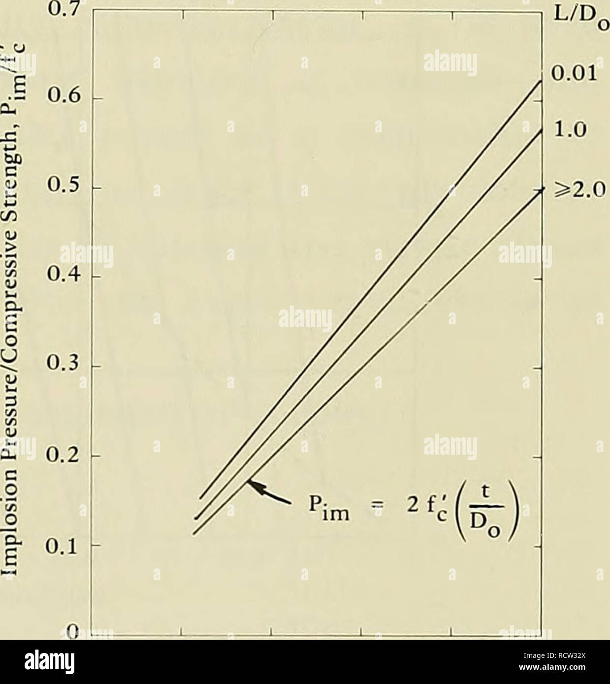 . Design for implosion of concrete cylinder structures under hydrostatic loading. Underwater concrete construction; Hydraulic structures. Although the cylinders were fabricated in rigid steel molds (Ref 2), the mold segments sprang slightly after the first disassembly. After References 2 and 4 were already published, a short cylinder section was mounted in a lathe to determine out-of-roundness more accurately than had been done previously. The inside and outside radius and the wall thickness varied by ±1/32 inch (1.6 mm). The out-of-roundness parameters are summarized in Table 1. Substituting Stock Photohttps://www.alamy.com/image-license-details/?v=1https://www.alamy.com/design-for-implosion-of-concrete-cylinder-structures-under-hydrostatic-loading-underwater-concrete-construction-hydraulic-structures-although-the-cylinders-were-fabricated-in-rigid-steel-molds-ref-2-the-mold-segments-sprang-slightly-after-the-first-disassembly-after-references-2-and-4-were-already-published-a-short-cylinder-section-was-mounted-in-a-lathe-to-determine-out-of-roundness-more-accurately-than-had-been-done-previously-the-inside-and-outside-radius-and-the-wall-thickness-varied-by-132-inch-16-mm-the-out-of-roundness-parameters-are-summarized-in-table-1-substituting-image231661890.html
RMRCW32X–. Design for implosion of concrete cylinder structures under hydrostatic loading. Underwater concrete construction; Hydraulic structures. Although the cylinders were fabricated in rigid steel molds (Ref 2), the mold segments sprang slightly after the first disassembly. After References 2 and 4 were already published, a short cylinder section was mounted in a lathe to determine out-of-roundness more accurately than had been done previously. The inside and outside radius and the wall thickness varied by ±1/32 inch (1.6 mm). The out-of-roundness parameters are summarized in Table 1. Substituting
 . Design for implosion of concrete cylinder structures under hydrostatic loading. Underwater concrete construction; Hydraulic structures. Wall thickness = U,,„ -0.08 in. Figure B-26. Idealized initial out-of-round shape for cylinders with n = 3.. Please note that these images are extracted from scanned page images that may have been digitally enhanced for readability - coloration and appearance of these illustrations may not perfectly resemble the original work.. Haynes, H. H; Naval Construction Battalion Center (Port Hueneme, Calif. ). Civil Engineering Laboratory. Port Hueneme, Calif. : Nava Stock Photohttps://www.alamy.com/image-license-details/?v=1https://www.alamy.com/design-for-implosion-of-concrete-cylinder-structures-under-hydrostatic-loading-underwater-concrete-construction-hydraulic-structures-wall-thickness-=-u-008-in-figure-b-26-idealized-initial-out-of-round-shape-for-cylinders-with-n-=-3-please-note-that-these-images-are-extracted-from-scanned-page-images-that-may-have-been-digitally-enhanced-for-readability-coloration-and-appearance-of-these-illustrations-may-not-perfectly-resemble-the-original-work-haynes-h-h-naval-construction-battalion-center-port-hueneme-calif-civil-engineering-laboratory-port-hueneme-calif-nava-image215986456.html
RMPFB0X0–. Design for implosion of concrete cylinder structures under hydrostatic loading. Underwater concrete construction; Hydraulic structures. Wall thickness = U,,„ -0.08 in. Figure B-26. Idealized initial out-of-round shape for cylinders with n = 3.. Please note that these images are extracted from scanned page images that may have been digitally enhanced for readability - coloration and appearance of these illustrations may not perfectly resemble the original work.. Haynes, H. H; Naval Construction Battalion Center (Port Hueneme, Calif. ). Civil Engineering Laboratory. Port Hueneme, Calif. : Nava
 . Design for implosion of concrete cylinder structures under hydrostatic loading. Underwater concrete construction; Hydraulic structures. four-arm spider potentiometer. lights (2 locations) top, end-closure ring concrete cylinder test specimen pressure vessel post-tensionmg chain (8 equally spaced) bottom end-closure —* high-pressure | J inlet and drain Figure B-3. Cross section of specimen, showing test setup. 42. Please note that these images are extracted from scanned page images that may have been digitally enhanced for readability - coloration and appearance of these illustrations ma Stock Photohttps://www.alamy.com/image-license-details/?v=1https://www.alamy.com/design-for-implosion-of-concrete-cylinder-structures-under-hydrostatic-loading-underwater-concrete-construction-hydraulic-structures-four-arm-spider-potentiometer-lights-2-locations-top-end-closure-ring-concrete-cylinder-test-specimen-pressure-vessel-post-tensionmg-chain-8-equally-spaced-bottom-end-closure-high-pressure-j-inlet-and-drain-figure-b-3-cross-section-of-specimen-showing-test-setup-42-please-note-that-these-images-are-extracted-from-scanned-page-images-that-may-have-been-digitally-enhanced-for-readability-coloration-and-appearance-of-these-illustrations-ma-image231661836.html
RMRCW310–. Design for implosion of concrete cylinder structures under hydrostatic loading. Underwater concrete construction; Hydraulic structures. four-arm spider potentiometer. lights (2 locations) top, end-closure ring concrete cylinder test specimen pressure vessel post-tensionmg chain (8 equally spaced) bottom end-closure —* high-pressure | J inlet and drain Figure B-3. Cross section of specimen, showing test setup. 42. Please note that these images are extracted from scanned page images that may have been digitally enhanced for readability - coloration and appearance of these illustrations ma
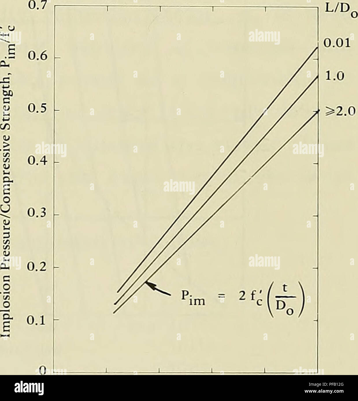 . Design for implosion of concrete cylinder structures under hydrostatic loading. Underwater concrete construction; Hydraulic structures. Although the cylinders were fabricated in rigid steel molds (Ref 2), the mold segments sprang slightly after the first disassembly. After References 2 and 4 were already published, a short cylinder section was mounted in a lathe to determine out-of-roundness more accurately than had been done previously. The inside and outside radius and the wall thickness varied by ±1/32 inch (1.6 mm). The out-of-roundness parameters are summarized in Table 1. Substituting Stock Photohttps://www.alamy.com/image-license-details/?v=1https://www.alamy.com/design-for-implosion-of-concrete-cylinder-structures-under-hydrostatic-loading-underwater-concrete-construction-hydraulic-structures-although-the-cylinders-were-fabricated-in-rigid-steel-molds-ref-2-the-mold-segments-sprang-slightly-after-the-first-disassembly-after-references-2-and-4-were-already-published-a-short-cylinder-section-was-mounted-in-a-lathe-to-determine-out-of-roundness-more-accurately-than-had-been-done-previously-the-inside-and-outside-radius-and-the-wall-thickness-varied-by-132-inch-16-mm-the-out-of-roundness-parameters-are-summarized-in-table-1-substituting-image215986584.html
RMPFB12G–. Design for implosion of concrete cylinder structures under hydrostatic loading. Underwater concrete construction; Hydraulic structures. Although the cylinders were fabricated in rigid steel molds (Ref 2), the mold segments sprang slightly after the first disassembly. After References 2 and 4 were already published, a short cylinder section was mounted in a lathe to determine out-of-roundness more accurately than had been done previously. The inside and outside radius and the wall thickness varied by ±1/32 inch (1.6 mm). The out-of-roundness parameters are summarized in Table 1. Substituting
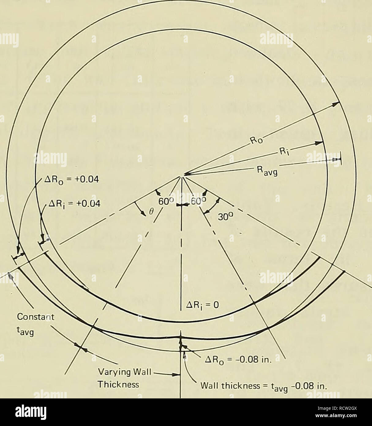 . Design for implosion of concrete cylinder structures under hydrostatic loading. Underwater concrete construction; Hydraulic structures. Wall thickness = U,,„ -0.08 in. Figure B-26. Idealized initial out-of-round shape for cylinders with n = 3.. Please note that these images are extracted from scanned page images that may have been digitally enhanced for readability - coloration and appearance of these illustrations may not perfectly resemble the original work.. Haynes, H. H; Naval Construction Battalion Center (Port Hueneme, Calif. ). Civil Engineering Laboratory. Port Hueneme, Calif. : Nava Stock Photohttps://www.alamy.com/image-license-details/?v=1https://www.alamy.com/design-for-implosion-of-concrete-cylinder-structures-under-hydrostatic-loading-underwater-concrete-construction-hydraulic-structures-wall-thickness-=-u-008-in-figure-b-26-idealized-initial-out-of-round-shape-for-cylinders-with-n-=-3-please-note-that-these-images-are-extracted-from-scanned-page-images-that-may-have-been-digitally-enhanced-for-readability-coloration-and-appearance-of-these-illustrations-may-not-perfectly-resemble-the-original-work-haynes-h-h-naval-construction-battalion-center-port-hueneme-calif-civil-engineering-laboratory-port-hueneme-calif-nava-image231661498.html
RMRCW2GX–. Design for implosion of concrete cylinder structures under hydrostatic loading. Underwater concrete construction; Hydraulic structures. Wall thickness = U,,„ -0.08 in. Figure B-26. Idealized initial out-of-round shape for cylinders with n = 3.. Please note that these images are extracted from scanned page images that may have been digitally enhanced for readability - coloration and appearance of these illustrations may not perfectly resemble the original work.. Haynes, H. H; Naval Construction Battalion Center (Port Hueneme, Calif. ). Civil Engineering Laboratory. Port Hueneme, Calif. : Nava
 . Design for implosion of concrete cylinder structures under hydrostatic loading. Underwater concrete construction; Hydraulic structures. Figure B-12. Fragments of failure hole from specimen 2-2.. Figure B-13. Post-implosion view of specimen 3-1 (t/D^ = 0.037, sim- ple support). 60. Please note that these images are extracted from scanned page images that may have been digitally enhanced for readability - coloration and appearance of these illustrations may not perfectly resemble the original work.. Haynes, H. H; Naval Construction Battalion Center (Port Hueneme, Calif. ). Civil Engineering La Stock Photohttps://www.alamy.com/image-license-details/?v=1https://www.alamy.com/design-for-implosion-of-concrete-cylinder-structures-under-hydrostatic-loading-underwater-concrete-construction-hydraulic-structures-figure-b-12-fragments-of-failure-hole-from-specimen-2-2-figure-b-13-post-implosion-view-of-specimen-3-1-td-=-0037-sim-ple-support-60-please-note-that-these-images-are-extracted-from-scanned-page-images-that-may-have-been-digitally-enhanced-for-readability-coloration-and-appearance-of-these-illustrations-may-not-perfectly-resemble-the-original-work-haynes-h-h-naval-construction-battalion-center-port-hueneme-calif-civil-engineering-la-image215986510.html
RMPFB0YX–. Design for implosion of concrete cylinder structures under hydrostatic loading. Underwater concrete construction; Hydraulic structures. Figure B-12. Fragments of failure hole from specimen 2-2.. Figure B-13. Post-implosion view of specimen 3-1 (t/D^ = 0.037, sim- ple support). 60. Please note that these images are extracted from scanned page images that may have been digitally enhanced for readability - coloration and appearance of these illustrations may not perfectly resemble the original work.. Haynes, H. H; Naval Construction Battalion Center (Port Hueneme, Calif. ). Civil Engineering La
 . Design for implosion of concrete cylinder structures under hydrostatic loading. Underwater concrete construction; Hydraulic structures. 270" t = 2.02 in. &». t = 1.99 in. 90° Figure B-6. Variation in wall thickness and mean radius at different locations on circumference at ^ = 0.4 (50 inches from bottom). Values are average of several specimens. 53. Please note that these images are extracted from scanned page images that may have been digitally enhanced for readability - coloration and appearance of these illustrations may not perfectly resemble the original work.. Haynes, H. H; Na Stock Photohttps://www.alamy.com/image-license-details/?v=1https://www.alamy.com/design-for-implosion-of-concrete-cylinder-structures-under-hydrostatic-loading-underwater-concrete-construction-hydraulic-structures-270quot-t-=-202-in-amp-t-=-199-in-90-figure-b-6-variation-in-wall-thickness-and-mean-radius-at-different-locations-on-circumference-at-=-04-50-inches-from-bottom-values-are-average-of-several-specimens-53-please-note-that-these-images-are-extracted-from-scanned-page-images-that-may-have-been-digitally-enhanced-for-readability-coloration-and-appearance-of-these-illustrations-may-not-perfectly-resemble-the-original-work-haynes-h-h-na-image231661811.html
RMRCW303–. Design for implosion of concrete cylinder structures under hydrostatic loading. Underwater concrete construction; Hydraulic structures. 270" t = 2.02 in. &». t = 1.99 in. 90° Figure B-6. Variation in wall thickness and mean radius at different locations on circumference at ^ = 0.4 (50 inches from bottom). Values are average of several specimens. 53. Please note that these images are extracted from scanned page images that may have been digitally enhanced for readability - coloration and appearance of these illustrations may not perfectly resemble the original work.. Haynes, H. H; Na
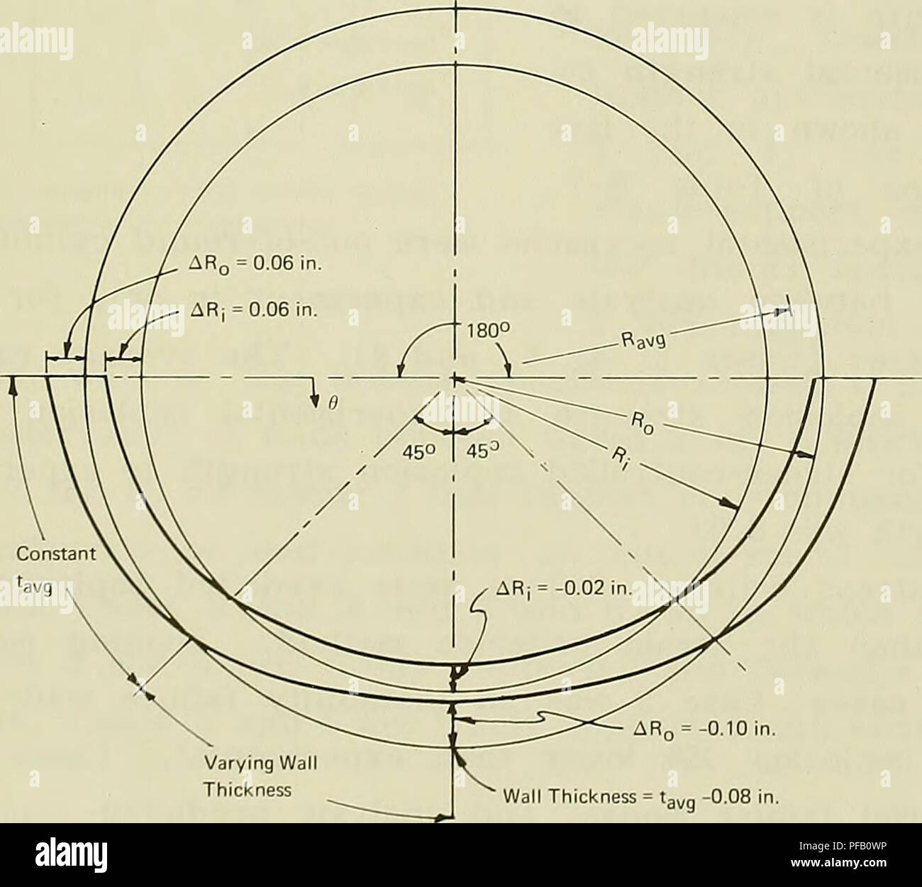 . Design for implosion of concrete cylinder structures under hydrostatic loading. Underwater concrete construction; Hydraulic structures. Wall thickness = U,,„ -0.08 in. Figure B-26. Idealized initial out-of-round shape for cylinders with n = 3.. AR„ = -0.10 in. Wall Thickness = ta„a -0-08 in. Figure B-27. Idealized initial out-of-round shape for cylinders with n = 2. 75. Please note that these images are extracted from scanned page images that may have been digitally enhanced for readability - coloration and appearance of these illustrations may not perfectly resemble the original work.. Hayn Stock Photohttps://www.alamy.com/image-license-details/?v=1https://www.alamy.com/design-for-implosion-of-concrete-cylinder-structures-under-hydrostatic-loading-underwater-concrete-construction-hydraulic-structures-wall-thickness-=-u-008-in-figure-b-26-idealized-initial-out-of-round-shape-for-cylinders-with-n-=-3-ar-=-010-in-wall-thickness-=-taa-0-08-in-figure-b-27-idealized-initial-out-of-round-shape-for-cylinders-with-n-=-2-75-please-note-that-these-images-are-extracted-from-scanned-page-images-that-may-have-been-digitally-enhanced-for-readability-coloration-and-appearance-of-these-illustrations-may-not-perfectly-resemble-the-original-work-hayn-image215986450.html
RMPFB0WP–. Design for implosion of concrete cylinder structures under hydrostatic loading. Underwater concrete construction; Hydraulic structures. Wall thickness = U,,„ -0.08 in. Figure B-26. Idealized initial out-of-round shape for cylinders with n = 3.. AR„ = -0.10 in. Wall Thickness = ta„a -0-08 in. Figure B-27. Idealized initial out-of-round shape for cylinders with n = 2. 75. Please note that these images are extracted from scanned page images that may have been digitally enhanced for readability - coloration and appearance of these illustrations may not perfectly resemble the original work.. Hayn
 . Design for implosion of concrete cylinder structures under hydrostatic loading. Underwater concrete construction; Hydraulic structures. Figure B-12. Fragments of failure hole from specimen 2-2.. Figure B-13. Post-implosion view of specimen 3-1 (t/D^ = 0.037, sim- ple support). 60. Please note that these images are extracted from scanned page images that may have been digitally enhanced for readability - coloration and appearance of these illustrations may not perfectly resemble the original work.. Haynes, H. H; Naval Construction Battalion Center (Port Hueneme, Calif. ). Civil Engineering La Stock Photohttps://www.alamy.com/image-license-details/?v=1https://www.alamy.com/design-for-implosion-of-concrete-cylinder-structures-under-hydrostatic-loading-underwater-concrete-construction-hydraulic-structures-figure-b-12-fragments-of-failure-hole-from-specimen-2-2-figure-b-13-post-implosion-view-of-specimen-3-1-td-=-0037-sim-ple-support-60-please-note-that-these-images-are-extracted-from-scanned-page-images-that-may-have-been-digitally-enhanced-for-readability-coloration-and-appearance-of-these-illustrations-may-not-perfectly-resemble-the-original-work-haynes-h-h-naval-construction-battalion-center-port-hueneme-calif-civil-engineering-la-image231661770.html
RMRCW2XJ–. Design for implosion of concrete cylinder structures under hydrostatic loading. Underwater concrete construction; Hydraulic structures. Figure B-12. Fragments of failure hole from specimen 2-2.. Figure B-13. Post-implosion view of specimen 3-1 (t/D^ = 0.037, sim- ple support). 60. Please note that these images are extracted from scanned page images that may have been digitally enhanced for readability - coloration and appearance of these illustrations may not perfectly resemble the original work.. Haynes, H. H; Naval Construction Battalion Center (Port Hueneme, Calif. ). Civil Engineering La
 . Design for implosion of concrete cylinder structures under hydrostatic loading. Underwater concrete construction; Hydraulic structures. 270" t = 2.02 in. &». t = 1.99 in. 90° Figure B-6. Variation in wall thickness and mean radius at different locations on circumference at ^ = 0.4 (50 inches from bottom). Values are average of several specimens. 53. Please note that these images are extracted from scanned page images that may have been digitally enhanced for readability - coloration and appearance of these illustrations may not perfectly resemble the original work.. Haynes, H. H; Na Stock Photohttps://www.alamy.com/image-license-details/?v=1https://www.alamy.com/design-for-implosion-of-concrete-cylinder-structures-under-hydrostatic-loading-underwater-concrete-construction-hydraulic-structures-270quot-t-=-202-in-amp-t-=-199-in-90-figure-b-6-variation-in-wall-thickness-and-mean-radius-at-different-locations-on-circumference-at-=-04-50-inches-from-bottom-values-are-average-of-several-specimens-53-please-note-that-these-images-are-extracted-from-scanned-page-images-that-may-have-been-digitally-enhanced-for-readability-coloration-and-appearance-of-these-illustrations-may-not-perfectly-resemble-the-original-work-haynes-h-h-na-image215986536.html
RMPFB10T–. Design for implosion of concrete cylinder structures under hydrostatic loading. Underwater concrete construction; Hydraulic structures. 270" t = 2.02 in. &». t = 1.99 in. 90° Figure B-6. Variation in wall thickness and mean radius at different locations on circumference at ^ = 0.4 (50 inches from bottom). Values are average of several specimens. 53. Please note that these images are extracted from scanned page images that may have been digitally enhanced for readability - coloration and appearance of these illustrations may not perfectly resemble the original work.. Haynes, H. H; Na
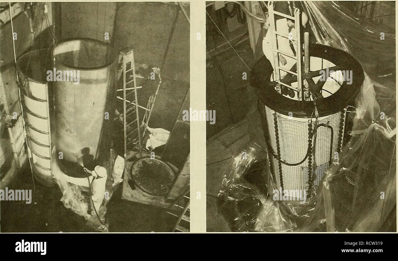 . Design for implosion of concrete cylinder structures under hydrostatic loading. Underwater concrete construction; Hydraulic structures. Figure B-1. Cylinder specimen being removed from mold. Figure B-2. Specimen partly assembled inside polyethy- lene tent. The specimens were moist-cured in this manner untU assembled for test. During assembly (Figure B-2) a tent of polyethylene film was used to maintain a high relative humidity environment around the speci- men to minimize shrinkage cracking. Keeping the cylinder in the moist environment assured the test conductors that the concrete was in a Stock Photohttps://www.alamy.com/image-license-details/?v=1https://www.alamy.com/design-for-implosion-of-concrete-cylinder-structures-under-hydrostatic-loading-underwater-concrete-construction-hydraulic-structures-figure-b-1-cylinder-specimen-being-removed-from-mold-figure-b-2-specimen-partly-assembled-inside-polyethy-lene-tent-the-specimens-were-moist-cured-in-this-manner-untu-assembled-for-test-during-assembly-figure-b-2-a-tent-of-polyethylene-film-was-used-to-maintain-a-high-relative-humidity-environment-around-the-speci-men-to-minimize-shrinkage-cracking-keeping-the-cylinder-in-the-moist-environment-assured-the-test-conductors-that-the-concrete-was-in-a-image231661845.html
RMRCW319–. Design for implosion of concrete cylinder structures under hydrostatic loading. Underwater concrete construction; Hydraulic structures. Figure B-1. Cylinder specimen being removed from mold. Figure B-2. Specimen partly assembled inside polyethy- lene tent. The specimens were moist-cured in this manner untU assembled for test. During assembly (Figure B-2) a tent of polyethylene film was used to maintain a high relative humidity environment around the speci- men to minimize shrinkage cracking. Keeping the cylinder in the moist environment assured the test conductors that the concrete was in a
 . Design for implosion of concrete cylinder structures under hydrostatic loading. Underwater concrete construction; Hydraulic structures. Figure B-1. Cylinder specimen being removed from mold. Figure B-2. Specimen partly assembled inside polyethy- lene tent. The specimens were moist-cured in this manner untU assembled for test. During assembly (Figure B-2) a tent of polyethylene film was used to maintain a high relative humidity environment around the speci- men to minimize shrinkage cracking. Keeping the cylinder in the moist environment assured the test conductors that the concrete was in a Stock Photohttps://www.alamy.com/image-license-details/?v=1https://www.alamy.com/design-for-implosion-of-concrete-cylinder-structures-under-hydrostatic-loading-underwater-concrete-construction-hydraulic-structures-figure-b-1-cylinder-specimen-being-removed-from-mold-figure-b-2-specimen-partly-assembled-inside-polyethy-lene-tent-the-specimens-were-moist-cured-in-this-manner-untu-assembled-for-test-during-assembly-figure-b-2-a-tent-of-polyethylene-film-was-used-to-maintain-a-high-relative-humidity-environment-around-the-speci-men-to-minimize-shrinkage-cracking-keeping-the-cylinder-in-the-moist-environment-assured-the-test-conductors-that-the-concrete-was-in-a-image215986560.html
RMPFB11M–. Design for implosion of concrete cylinder structures under hydrostatic loading. Underwater concrete construction; Hydraulic structures. Figure B-1. Cylinder specimen being removed from mold. Figure B-2. Specimen partly assembled inside polyethy- lene tent. The specimens were moist-cured in this manner untU assembled for test. During assembly (Figure B-2) a tent of polyethylene film was used to maintain a high relative humidity environment around the speci- men to minimize shrinkage cracking. Keeping the cylinder in the moist environment assured the test conductors that the concrete was in a
 . Design for implosion of concrete cylinder structures under hydrostatic loading. Underwater concrete construction; Hydraulic structures. Wall thickness = U,,„ -0.08 in. Figure B-26. Idealized initial out-of-round shape for cylinders with n = 3.. AR„ = -0.10 in. Wall Thickness = ta„a -0-08 in. Figure B-27. Idealized initial out-of-round shape for cylinders with n = 2. 75. Please note that these images are extracted from scanned page images that may have been digitally enhanced for readability - coloration and appearance of these illustrations may not perfectly resemble the original work.. Hayn Stock Photohttps://www.alamy.com/image-license-details/?v=1https://www.alamy.com/design-for-implosion-of-concrete-cylinder-structures-under-hydrostatic-loading-underwater-concrete-construction-hydraulic-structures-wall-thickness-=-u-008-in-figure-b-26-idealized-initial-out-of-round-shape-for-cylinders-with-n-=-3-ar-=-010-in-wall-thickness-=-taa-0-08-in-figure-b-27-idealized-initial-out-of-round-shape-for-cylinders-with-n-=-2-75-please-note-that-these-images-are-extracted-from-scanned-page-images-that-may-have-been-digitally-enhanced-for-readability-coloration-and-appearance-of-these-illustrations-may-not-perfectly-resemble-the-original-work-hayn-image231661490.html
RMRCW2GJ–. Design for implosion of concrete cylinder structures under hydrostatic loading. Underwater concrete construction; Hydraulic structures. Wall thickness = U,,„ -0.08 in. Figure B-26. Idealized initial out-of-round shape for cylinders with n = 3.. AR„ = -0.10 in. Wall Thickness = ta„a -0-08 in. Figure B-27. Idealized initial out-of-round shape for cylinders with n = 2. 75. Please note that these images are extracted from scanned page images that may have been digitally enhanced for readability - coloration and appearance of these illustrations may not perfectly resemble the original work.. Hayn
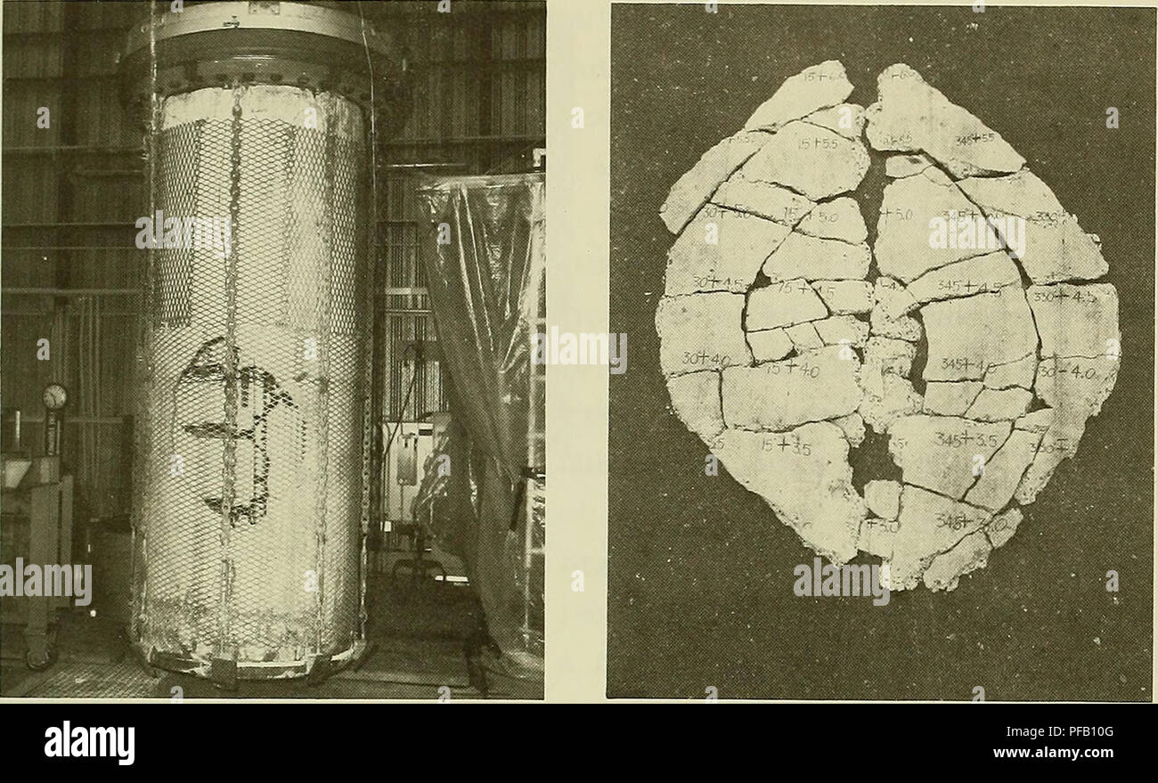 . Design for implosion of concrete cylinder structures under hydrostatic loading. Underwater concrete construction; Hydraulic structures. Figure B-8. Post-implosion view of specimen 1-1 (t/D^ = 0.024, sim- ple support). Figure B-9. Fragments of failure hole from specimen 1-1.. Please note that these images are extracted from scanned page images that may have been digitally enhanced for readability - coloration and appearance of these illustrations may not perfectly resemble the original work.. Haynes, H. H; Naval Construction Battalion Center (Port Hueneme, Calif. ). Civil Engineering Laborato Stock Photohttps://www.alamy.com/image-license-details/?v=1https://www.alamy.com/design-for-implosion-of-concrete-cylinder-structures-under-hydrostatic-loading-underwater-concrete-construction-hydraulic-structures-figure-b-8-post-implosion-view-of-specimen-1-1-td-=-0024-sim-ple-support-figure-b-9-fragments-of-failure-hole-from-specimen-1-1-please-note-that-these-images-are-extracted-from-scanned-page-images-that-may-have-been-digitally-enhanced-for-readability-coloration-and-appearance-of-these-illustrations-may-not-perfectly-resemble-the-original-work-haynes-h-h-naval-construction-battalion-center-port-hueneme-calif-civil-engineering-laborato-image215986528.html
RMPFB10G–. Design for implosion of concrete cylinder structures under hydrostatic loading. Underwater concrete construction; Hydraulic structures. Figure B-8. Post-implosion view of specimen 1-1 (t/D^ = 0.024, sim- ple support). Figure B-9. Fragments of failure hole from specimen 1-1.. Please note that these images are extracted from scanned page images that may have been digitally enhanced for readability - coloration and appearance of these illustrations may not perfectly resemble the original work.. Haynes, H. H; Naval Construction Battalion Center (Port Hueneme, Calif. ). Civil Engineering Laborato
 . Design for implosion of concrete cylinder structures under hydrostatic loading. Underwater concrete construction; Hydraulic structures. (f) of about 0.16, at a distance of 2 inches (50 mm) away from the stif- feners. The test specimens had a clear length between stiffeners of 127 inches (3220 mm). After accounting for the compHance of the stiffener, the "actual" length of the cylinder appeared to be about 130 inches (3300 mm); hence, the effect of stiffener compliance was small.. Figure B-16. Local failure of specimen 5-2 (t/D = 0.063, free support). To test for possible reduction Stock Photohttps://www.alamy.com/image-license-details/?v=1https://www.alamy.com/design-for-implosion-of-concrete-cylinder-structures-under-hydrostatic-loading-underwater-concrete-construction-hydraulic-structures-f-of-about-016-at-a-distance-of-2-inches-50-mm-away-from-the-stif-feners-the-test-specimens-had-a-clear-length-between-stiffeners-of-127-inches-3220-mm-after-accounting-for-the-comphance-of-the-stiffener-the-quotactualquot-length-of-the-cylinder-appeared-to-be-about-130-inches-3300-mm-hence-the-effect-of-stiffener-compliance-was-small-figure-b-16-local-failure-of-specimen-5-2-td-=-0063-free-support-to-test-for-possible-reduction-image231661749.html
RMRCW2WW–. Design for implosion of concrete cylinder structures under hydrostatic loading. Underwater concrete construction; Hydraulic structures. (f) of about 0.16, at a distance of 2 inches (50 mm) away from the stif- feners. The test specimens had a clear length between stiffeners of 127 inches (3220 mm). After accounting for the compHance of the stiffener, the "actual" length of the cylinder appeared to be about 130 inches (3300 mm); hence, the effect of stiffener compliance was small.. Figure B-16. Local failure of specimen 5-2 (t/D = 0.063, free support). To test for possible reduction
 . Design for implosion of concrete cylinder structures under hydrostatic loading. Underwater concrete construction; Hydraulic structures. (f) of about 0.16, at a distance of 2 inches (50 mm) away from the stif- feners. The test specimens had a clear length between stiffeners of 127 inches (3220 mm). After accounting for the compHance of the stiffener, the "actual" length of the cylinder appeared to be about 130 inches (3300 mm); hence, the effect of stiffener compliance was small.. Figure B-16. Local failure of specimen 5-2 (t/D = 0.063, free support). To test for possible reduction Stock Photohttps://www.alamy.com/image-license-details/?v=1https://www.alamy.com/design-for-implosion-of-concrete-cylinder-structures-under-hydrostatic-loading-underwater-concrete-construction-hydraulic-structures-f-of-about-016-at-a-distance-of-2-inches-50-mm-away-from-the-stif-feners-the-test-specimens-had-a-clear-length-between-stiffeners-of-127-inches-3220-mm-after-accounting-for-the-comphance-of-the-stiffener-the-quotactualquot-length-of-the-cylinder-appeared-to-be-about-130-inches-3300-mm-hence-the-effect-of-stiffener-compliance-was-small-figure-b-16-local-failure-of-specimen-5-2-td-=-0063-free-support-to-test-for-possible-reduction-image215986500.html
RMPFB0YG–. Design for implosion of concrete cylinder structures under hydrostatic loading. Underwater concrete construction; Hydraulic structures. (f) of about 0.16, at a distance of 2 inches (50 mm) away from the stif- feners. The test specimens had a clear length between stiffeners of 127 inches (3220 mm). After accounting for the compHance of the stiffener, the "actual" length of the cylinder appeared to be about 130 inches (3300 mm); hence, the effect of stiffener compliance was small.. Figure B-16. Local failure of specimen 5-2 (t/D = 0.063, free support). To test for possible reduction
 . Design for implosion of concrete cylinder structures under hydrostatic loading. Underwater concrete construction; Hydraulic structures. Figure B-8. Post-implosion view of specimen 1-1 (t/D^ = 0.024, sim- ple support). Figure B-9. Fragments of failure hole from specimen 1-1.. Please note that these images are extracted from scanned page images that may have been digitally enhanced for readability - coloration and appearance of these illustrations may not perfectly resemble the original work.. Haynes, H. H; Naval Construction Battalion Center (Port Hueneme, Calif. ). Civil Engineering Laborato Stock Photohttps://www.alamy.com/image-license-details/?v=1https://www.alamy.com/design-for-implosion-of-concrete-cylinder-structures-under-hydrostatic-loading-underwater-concrete-construction-hydraulic-structures-figure-b-8-post-implosion-view-of-specimen-1-1-td-=-0024-sim-ple-support-figure-b-9-fragments-of-failure-hole-from-specimen-1-1-please-note-that-these-images-are-extracted-from-scanned-page-images-that-may-have-been-digitally-enhanced-for-readability-coloration-and-appearance-of-these-illustrations-may-not-perfectly-resemble-the-original-work-haynes-h-h-naval-construction-battalion-center-port-hueneme-calif-civil-engineering-laborato-image231661795.html
RMRCW2YF–. Design for implosion of concrete cylinder structures under hydrostatic loading. Underwater concrete construction; Hydraulic structures. Figure B-8. Post-implosion view of specimen 1-1 (t/D^ = 0.024, sim- ple support). Figure B-9. Fragments of failure hole from specimen 1-1.. Please note that these images are extracted from scanned page images that may have been digitally enhanced for readability - coloration and appearance of these illustrations may not perfectly resemble the original work.. Haynes, H. H; Naval Construction Battalion Center (Port Hueneme, Calif. ). Civil Engineering Laborato
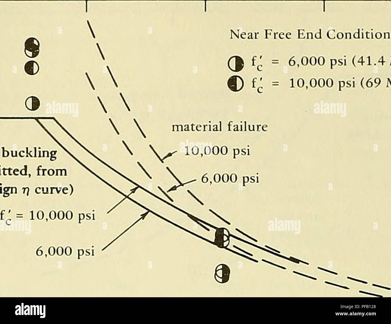 . Design for implosion of concrete cylinder structures under hydrostatic loading. Underwater concrete construction; Hydraulic structures. elastic buckling Near Free End Condition (J f^; = 6,000 psi (41.4 MPa) C) fc = 10,000 psi (69 MPa) inelastic buckling (curves not fitted, from Figure 8 design r) curve). Please note that these images are extracted from scanned page images that may have been digitally enhanced for readability - coloration and appearance of these illustrations may not perfectly resemble the original work.. Haynes, H. H; Naval Construction Battalion Center (Port Hueneme, Cal Stock Photohttps://www.alamy.com/image-license-details/?v=1https://www.alamy.com/design-for-implosion-of-concrete-cylinder-structures-under-hydrostatic-loading-underwater-concrete-construction-hydraulic-structures-elastic-buckling-near-free-end-condition-j-f-=-6000-psi-414-mpa-c-fc-=-10000-psi-69-mpa-inelastic-buckling-curves-not-fitted-from-figure-8-design-r-curve-please-note-that-these-images-are-extracted-from-scanned-page-images-that-may-have-been-digitally-enhanced-for-readability-coloration-and-appearance-of-these-illustrations-may-not-perfectly-resemble-the-original-work-haynes-h-h-naval-construction-battalion-center-port-hueneme-cal-image215986576.html
RMPFB128–. Design for implosion of concrete cylinder structures under hydrostatic loading. Underwater concrete construction; Hydraulic structures. elastic buckling Near Free End Condition (J f^; = 6,000 psi (41.4 MPa) C) fc = 10,000 psi (69 MPa) inelastic buckling (curves not fitted, from Figure 8 design r) curve). Please note that these images are extracted from scanned page images that may have been digitally enhanced for readability - coloration and appearance of these illustrations may not perfectly resemble the original work.. Haynes, H. H; Naval Construction Battalion Center (Port Hueneme, Cal
 . Design for implosion of concrete cylinder structures under hydrostatic loading. Underwater concrete construction; Hydraulic structures. elastic buckling Near Free End Condition (J f^; = 6,000 psi (41.4 MPa) C) fc = 10,000 psi (69 MPa) inelastic buckling (curves not fitted, from Figure 8 design r) curve). Please note that these images are extracted from scanned page images that may have been digitally enhanced for readability - coloration and appearance of these illustrations may not perfectly resemble the original work.. Haynes, H. H; Naval Construction Battalion Center (Port Hueneme, Cal Stock Photohttps://www.alamy.com/image-license-details/?v=1https://www.alamy.com/design-for-implosion-of-concrete-cylinder-structures-under-hydrostatic-loading-underwater-concrete-construction-hydraulic-structures-elastic-buckling-near-free-end-condition-j-f-=-6000-psi-414-mpa-c-fc-=-10000-psi-69-mpa-inelastic-buckling-curves-not-fitted-from-figure-8-design-r-curve-please-note-that-these-images-are-extracted-from-scanned-page-images-that-may-have-been-digitally-enhanced-for-readability-coloration-and-appearance-of-these-illustrations-may-not-perfectly-resemble-the-original-work-haynes-h-h-naval-construction-battalion-center-port-hueneme-cal-image231661875.html
RMRCW32B–. Design for implosion of concrete cylinder structures under hydrostatic loading. Underwater concrete construction; Hydraulic structures. elastic buckling Near Free End Condition (J f^; = 6,000 psi (41.4 MPa) C) fc = 10,000 psi (69 MPa) inelastic buckling (curves not fitted, from Figure 8 design r) curve). Please note that these images are extracted from scanned page images that may have been digitally enhanced for readability - coloration and appearance of these illustrations may not perfectly resemble the original work.. Haynes, H. H; Naval Construction Battalion Center (Port Hueneme, Cal
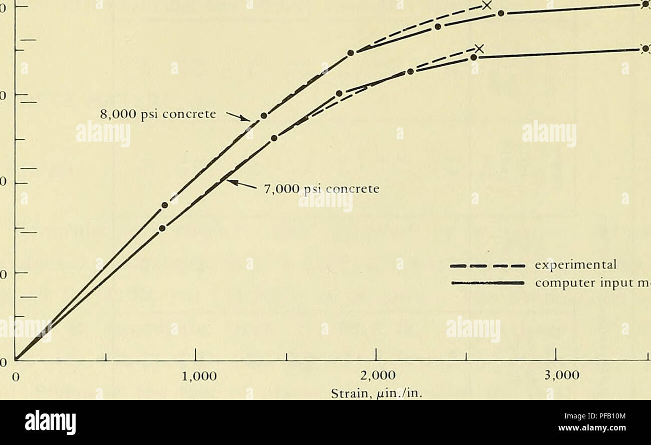 . Design for implosion of concrete cylinder structures under hydrostatic loading. Underwater concrete construction; Hydraulic structures. 10,000 S. 6,000. —.— experimental ^-^ computer input model Figure B-7. Uniaxial compressive stress-strain relationship for concrete. The water-to-cement ratio was 0.37 and a retardant admixture, E42 Master Builder, was used at 4.1 ounces (0.12 kg-) per 100 pounds (45.4 kg) of cement. The compressive strength of this mix was 5,520 psi (38.1 MPa) at 7 days taken from three 3x6-inch (76xl52-mm) control cylinders. TEST RESULTS Implosion Test conditions and implo Stock Photohttps://www.alamy.com/image-license-details/?v=1https://www.alamy.com/design-for-implosion-of-concrete-cylinder-structures-under-hydrostatic-loading-underwater-concrete-construction-hydraulic-structures-10000-s-6000-experimental-computer-input-model-figure-b-7-uniaxial-compressive-stress-strain-relationship-for-concrete-the-water-to-cement-ratio-was-037-and-a-retardant-admixture-e42-master-builder-was-used-at-41-ounces-012-kg-per-100-pounds-454-kg-of-cement-the-compressive-strength-of-this-mix-was-5520-psi-381-mpa-at-7-days-taken-from-three-3x6-inch-76xl52-mm-control-cylinders-test-results-implosion-test-conditions-and-implo-image215986532.html
RMPFB10M–. Design for implosion of concrete cylinder structures under hydrostatic loading. Underwater concrete construction; Hydraulic structures. 10,000 S. 6,000. —.— experimental ^-^ computer input model Figure B-7. Uniaxial compressive stress-strain relationship for concrete. The water-to-cement ratio was 0.37 and a retardant admixture, E42 Master Builder, was used at 4.1 ounces (0.12 kg-) per 100 pounds (45.4 kg) of cement. The compressive strength of this mix was 5,520 psi (38.1 MPa) at 7 days taken from three 3x6-inch (76xl52-mm) control cylinders. TEST RESULTS Implosion Test conditions and implo
 . Design for implosion of concrete cylinder structures under hydrostatic loading. Underwater concrete construction; Hydraulic structures. Radius deviation scale: 0 0.2 in. I H 0 4 mm i = 0.4 p = 0 psi. Figure B-5. Initial cross-section shape (superimposed to show relative changes in wall thickness and flat spots) for specimen 2-3, showing radius deviations of inner and outer wall surfaces at 0 psi and i, = 0.4 (50 inches from bottom). 52. Please note that these images are extracted from scanned page images that may have been digitally enhanced for readability - coloration and appearance of the Stock Photohttps://www.alamy.com/image-license-details/?v=1https://www.alamy.com/design-for-implosion-of-concrete-cylinder-structures-under-hydrostatic-loading-underwater-concrete-construction-hydraulic-structures-radius-deviation-scale-0-02-in-i-h-0-4-mm-i-=-04-p-=-0-psi-figure-b-5-initial-cross-section-shape-superimposed-to-show-relative-changes-in-wall-thickness-and-flat-spots-for-specimen-2-3-showing-radius-deviations-of-inner-and-outer-wall-surfaces-at-0-psi-and-i-=-04-50-inches-from-bottom-52-please-note-that-these-images-are-extracted-from-scanned-page-images-that-may-have-been-digitally-enhanced-for-readability-coloration-and-appearance-of-the-image231661820.html
RMRCW30C–. Design for implosion of concrete cylinder structures under hydrostatic loading. Underwater concrete construction; Hydraulic structures. Radius deviation scale: 0 0.2 in. I H 0 4 mm i = 0.4 p = 0 psi. Figure B-5. Initial cross-section shape (superimposed to show relative changes in wall thickness and flat spots) for specimen 2-3, showing radius deviations of inner and outer wall surfaces at 0 psi and i, = 0.4 (50 inches from bottom). 52. Please note that these images are extracted from scanned page images that may have been digitally enhanced for readability - coloration and appearance of the
 . Design for implosion of concrete cylinder structures under hydrostatic loading. Underwater concrete construction; Hydraulic structures. perfect cylinder, Case 3 experimental average analytical stress control failure strain control failure out-of-round cylinder, Case 4. t/Dp = 0.037 L/Dj,= 2,35 simple support t = 1.97 in. 0.10 Radial Displacements, w (in.) Figure B-22. Radial displacement behavior at midlength of Group 3 cylinders having t/D = 0.037 and simple support.. Please note that these images are extracted from scanned page images that may have been digitally enhanced for readability - Stock Photohttps://www.alamy.com/image-license-details/?v=1https://www.alamy.com/design-for-implosion-of-concrete-cylinder-structures-under-hydrostatic-loading-underwater-concrete-construction-hydraulic-structures-perfect-cylinder-case-3-experimental-average-analytical-stress-control-failure-strain-control-failure-out-of-round-cylinder-case-4-tdp-=-0037-ldj=-235-simple-support-t-=-197-in-010-radial-displacements-w-in-figure-b-22-radial-displacement-behavior-at-midlength-of-group-3-cylinders-having-td-=-0037-and-simple-support-please-note-that-these-images-are-extracted-from-scanned-page-images-that-may-have-been-digitally-enhanced-for-readability-image215986471.html
RMPFB0XF–. Design for implosion of concrete cylinder structures under hydrostatic loading. Underwater concrete construction; Hydraulic structures. perfect cylinder, Case 3 experimental average analytical stress control failure strain control failure out-of-round cylinder, Case 4. t/Dp = 0.037 L/Dj,= 2,35 simple support t = 1.97 in. 0.10 Radial Displacements, w (in.) Figure B-22. Radial displacement behavior at midlength of Group 3 cylinders having t/D = 0.037 and simple support.. Please note that these images are extracted from scanned page images that may have been digitally enhanced for readability -
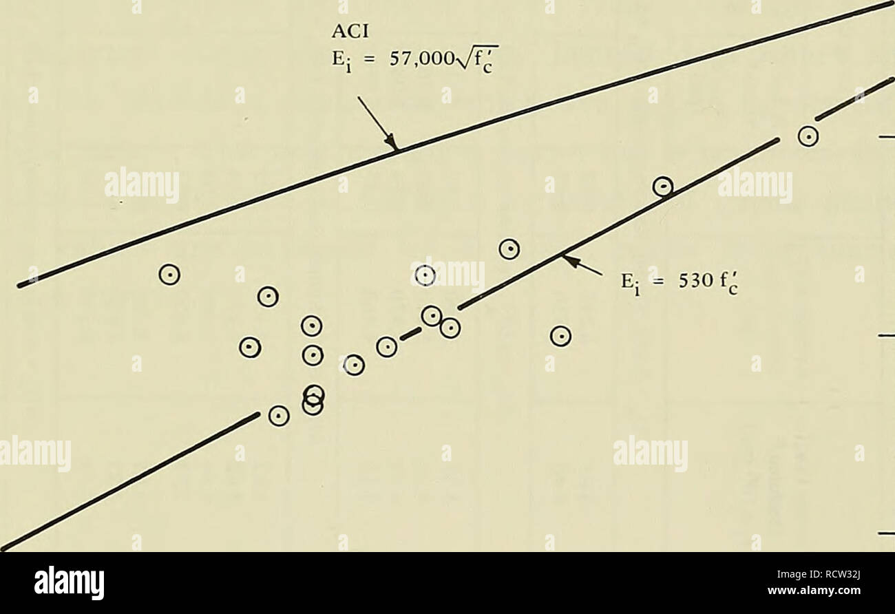 . Design for implosion of concrete cylinder structures under hydrostatic loading. Underwater concrete construction; Hydraulic structures. The empirical expression has the rational basis of being derived from the parabolic relationship for tangent modulus as follows: 2 f , where E = tangent modulus £ = ultimate strain (experimental average was 0.0025) and the fitted condition of a = 0.56 f when E. = E^. c it ACI E: = ST.OOOs/fT. 1 â 'â¢^ c 0 6xl2-in. control cylinder 7,000 8,000 Compressive Strength, f^ (psi) 9,000 Figure 4. Relationship between E: and f'. 11. Please note that these images are Stock Photohttps://www.alamy.com/image-license-details/?v=1https://www.alamy.com/design-for-implosion-of-concrete-cylinder-structures-under-hydrostatic-loading-underwater-concrete-construction-hydraulic-structures-the-empirical-expression-has-the-rational-basis-of-being-derived-from-the-parabolic-relationship-for-tangent-modulus-as-follows-2-f-where-e-=-tangent-modulus-=-ultimate-strain-experimental-average-was-00025-and-the-fitted-condition-of-a-=-056-f-when-e-=-e-c-it-aci-e-=-stooosft-1-c-0-6xl2-in-control-cylinder-7000-8000-compressive-strength-f-psi-9000-figure-4-relationship-between-e-and-f-11-please-note-that-these-images-are-image231661882.html
RMRCW32J–. Design for implosion of concrete cylinder structures under hydrostatic loading. Underwater concrete construction; Hydraulic structures. The empirical expression has the rational basis of being derived from the parabolic relationship for tangent modulus as follows: 2 f , where E = tangent modulus £ = ultimate strain (experimental average was 0.0025) and the fitted condition of a = 0.56 f when E. = E^. c it ACI E: = ST.OOOs/fT. 1 â 'â¢^ c 0 6xl2-in. control cylinder 7,000 8,000 Compressive Strength, f^ (psi) 9,000 Figure 4. Relationship between E: and f'. 11. Please note that these images are
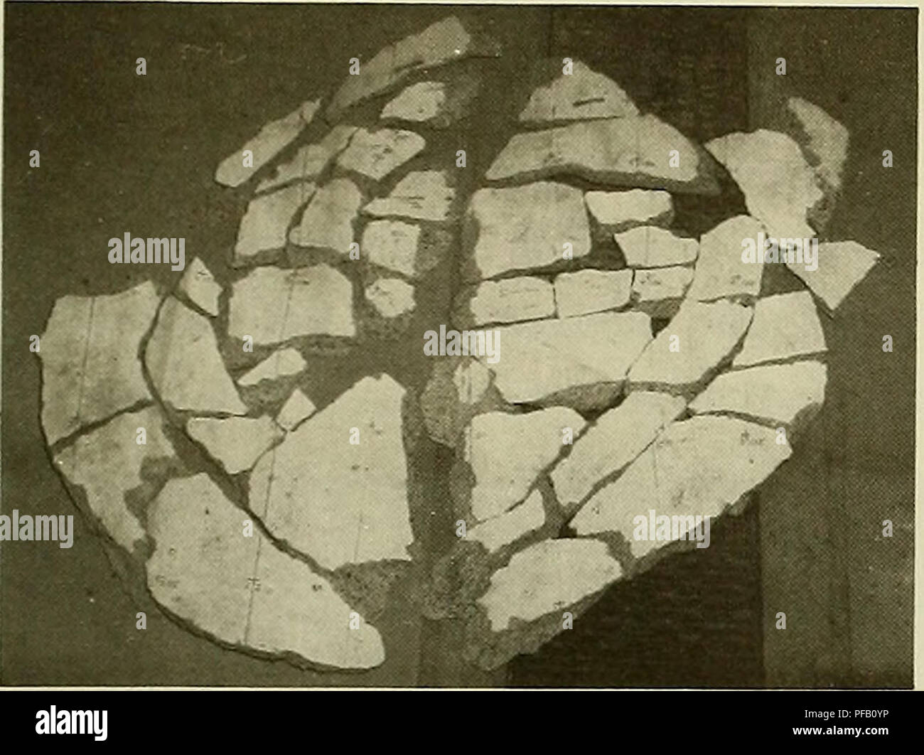 . Design for implosion of concrete cylinder structures under hydrostatic loading. Underwater concrete construction; Hydraulic structures. Figure B-14. Fragments of failure hole from specimen 3-1. For simple-support specimens, the ideal 4) of zero was not obtained. The radial deflection of the steel stiffener provided some compliance. The stiffener deflection was calculated to be about 0.01 inch (0.3 mm) at a pressure load of 500 psi (3.5 MPa), or a 4) of 0.08. Measured radial deflections showed values about 0.02 inch (0.5 mm), a )///// "°'^ ^ %^ 120 J /^J^ ^ y- 100 80 —- 7 J- 60 Stock Photohttps://www.alamy.com/image-license-details/?v=1https://www.alamy.com/design-for-implosion-of-concrete-cylinder-structures-under-hydrostatic-loading-underwater-concrete-construction-hydraulic-structures-figure-b-14-fragments-of-failure-hole-from-specimen-3-1-for-simple-support-specimens-the-ideal-4-of-zero-was-not-obtained-the-radial-deflection-of-the-steel-stiffener-provided-some-compliance-the-stiffener-deflection-was-calculated-to-be-about-001-inch-03-mm-at-a-pressure-load-of-500-psi-35-mpa-or-a-4-of-008-measured-radial-deflections-showed-values-about-002-inch-05-mm-a-quot-120-j-j-y-100-80-7-j-60-image215986506.html
RMPFB0YP–. Design for implosion of concrete cylinder structures under hydrostatic loading. Underwater concrete construction; Hydraulic structures. Figure B-14. Fragments of failure hole from specimen 3-1. For simple-support specimens, the ideal 4) of zero was not obtained. The radial deflection of the steel stiffener provided some compliance. The stiffener deflection was calculated to be about 0.01 inch (0.3 mm) at a pressure load of 500 psi (3.5 MPa), or a 4) of 0.08. Measured radial deflections showed values about 0.02 inch (0.5 mm), a )///// "°'^ ^ %^ 120 J /^J^ ^ y- 100 80 —- 7 J- 60
 . Design for implosion of concrete cylinder structures under hydrostatic loading. Underwater concrete construction; Hydraulic structures. perfect cylinder, Case 3 experimental average analytical stress control failure strain control failure out-of-round cylinder, Case 4. t/Dp = 0.037 L/Dj,= 2,35 simple support t = 1.97 in. 0.10 Radial Displacements, w (in.) Figure B-22. Radial displacement behavior at midlength of Group 3 cylinders having t/D = 0.037 and simple support.. Please note that these images are extracted from scanned page images that may have been digitally enhanced for readability - Stock Photohttps://www.alamy.com/image-license-details/?v=1https://www.alamy.com/design-for-implosion-of-concrete-cylinder-structures-under-hydrostatic-loading-underwater-concrete-construction-hydraulic-structures-perfect-cylinder-case-3-experimental-average-analytical-stress-control-failure-strain-control-failure-out-of-round-cylinder-case-4-tdp-=-0037-ldj=-235-simple-support-t-=-197-in-010-radial-displacements-w-in-figure-b-22-radial-displacement-behavior-at-midlength-of-group-3-cylinders-having-td-=-0037-and-simple-support-please-note-that-these-images-are-extracted-from-scanned-page-images-that-may-have-been-digitally-enhanced-for-readability-image231661707.html
RMRCW2TB–. Design for implosion of concrete cylinder structures under hydrostatic loading. Underwater concrete construction; Hydraulic structures. perfect cylinder, Case 3 experimental average analytical stress control failure strain control failure out-of-round cylinder, Case 4. t/Dp = 0.037 L/Dj,= 2,35 simple support t = 1.97 in. 0.10 Radial Displacements, w (in.) Figure B-22. Radial displacement behavior at midlength of Group 3 cylinders having t/D = 0.037 and simple support.. Please note that these images are extracted from scanned page images that may have been digitally enhanced for readability -
 . Design for implosion of concrete cylinder structures under hydrostatic loading. Underwater concrete construction; Hydraulic structures. The empirical expression has the rational basis of being derived from the parabolic relationship for tangent modulus as follows: 2 f , where E = tangent modulus £ = ultimate strain (experimental average was 0.0025) and the fitted condition of a = 0.56 f when E. = E^. c it ACI E: = ST.OOOs/fT. 1 â 'â¢^ c 0 6xl2-in. control cylinder 7,000 8,000 Compressive Strength, f^ (psi) 9,000 Figure 4. Relationship between E: and f'. 11. Please note that these images are Stock Photohttps://www.alamy.com/image-license-details/?v=1https://www.alamy.com/design-for-implosion-of-concrete-cylinder-structures-under-hydrostatic-loading-underwater-concrete-construction-hydraulic-structures-the-empirical-expression-has-the-rational-basis-of-being-derived-from-the-parabolic-relationship-for-tangent-modulus-as-follows-2-f-where-e-=-tangent-modulus-=-ultimate-strain-experimental-average-was-00025-and-the-fitted-condition-of-a-=-056-f-when-e-=-e-c-it-aci-e-=-stooosft-1-c-0-6xl2-in-control-cylinder-7000-8000-compressive-strength-f-psi-9000-figure-4-relationship-between-e-and-f-11-please-note-that-these-images-are-image215986580.html
RMPFB12C–. Design for implosion of concrete cylinder structures under hydrostatic loading. Underwater concrete construction; Hydraulic structures. The empirical expression has the rational basis of being derived from the parabolic relationship for tangent modulus as follows: 2 f , where E = tangent modulus £ = ultimate strain (experimental average was 0.0025) and the fitted condition of a = 0.56 f when E. = E^. c it ACI E: = ST.OOOs/fT. 1 â 'â¢^ c 0 6xl2-in. control cylinder 7,000 8,000 Compressive Strength, f^ (psi) 9,000 Figure 4. Relationship between E: and f'. 11. Please note that these images are
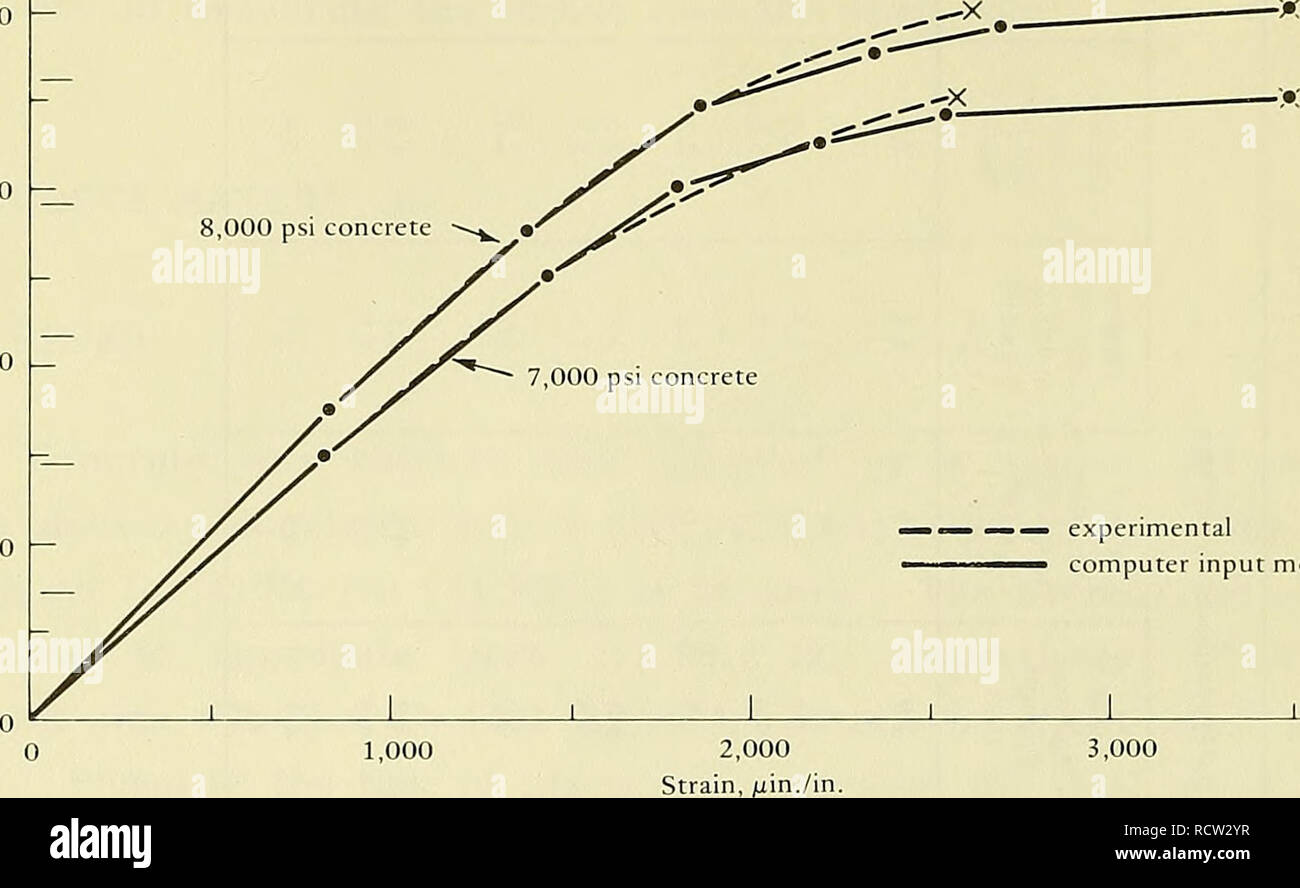 . Design for implosion of concrete cylinder structures under hydrostatic loading. Underwater concrete construction; Hydraulic structures. 10,000 S. 6,000. —.— experimental ^-^ computer input model Figure B-7. Uniaxial compressive stress-strain relationship for concrete. The water-to-cement ratio was 0.37 and a retardant admixture, E42 Master Builder, was used at 4.1 ounces (0.12 kg-) per 100 pounds (45.4 kg) of cement. The compressive strength of this mix was 5,520 psi (38.1 MPa) at 7 days taken from three 3x6-inch (76xl52-mm) control cylinders. TEST RESULTS Implosion Test conditions and implo Stock Photohttps://www.alamy.com/image-license-details/?v=1https://www.alamy.com/design-for-implosion-of-concrete-cylinder-structures-under-hydrostatic-loading-underwater-concrete-construction-hydraulic-structures-10000-s-6000-experimental-computer-input-model-figure-b-7-uniaxial-compressive-stress-strain-relationship-for-concrete-the-water-to-cement-ratio-was-037-and-a-retardant-admixture-e42-master-builder-was-used-at-41-ounces-012-kg-per-100-pounds-454-kg-of-cement-the-compressive-strength-of-this-mix-was-5520-psi-381-mpa-at-7-days-taken-from-three-3x6-inch-76xl52-mm-control-cylinders-test-results-implosion-test-conditions-and-implo-image231661803.html
RMRCW2YR–. Design for implosion of concrete cylinder structures under hydrostatic loading. Underwater concrete construction; Hydraulic structures. 10,000 S. 6,000. —.— experimental ^-^ computer input model Figure B-7. Uniaxial compressive stress-strain relationship for concrete. The water-to-cement ratio was 0.37 and a retardant admixture, E42 Master Builder, was used at 4.1 ounces (0.12 kg-) per 100 pounds (45.4 kg) of cement. The compressive strength of this mix was 5,520 psi (38.1 MPa) at 7 days taken from three 3x6-inch (76xl52-mm) control cylinders. TEST RESULTS Implosion Test conditions and implo
 . Design for implosion of concrete cylinder structures under hydrostatic loading. Underwater concrete construction; Hydraulic structures. Radius deviation scale: 0 0.2 in. I H 0 4 mm i = 0.4 p = 0 psi. Figure B-5. Initial cross-section shape (superimposed to show relative changes in wall thickness and flat spots) for specimen 2-3, showing radius deviations of inner and outer wall surfaces at 0 psi and i, = 0.4 (50 inches from bottom). 52. Please note that these images are extracted from scanned page images that may have been digitally enhanced for readability - coloration and appearance of the Stock Photohttps://www.alamy.com/image-license-details/?v=1https://www.alamy.com/design-for-implosion-of-concrete-cylinder-structures-under-hydrostatic-loading-underwater-concrete-construction-hydraulic-structures-radius-deviation-scale-0-02-in-i-h-0-4-mm-i-=-04-p-=-0-psi-figure-b-5-initial-cross-section-shape-superimposed-to-show-relative-changes-in-wall-thickness-and-flat-spots-for-specimen-2-3-showing-radius-deviations-of-inner-and-outer-wall-surfaces-at-0-psi-and-i-=-04-50-inches-from-bottom-52-please-note-that-these-images-are-extracted-from-scanned-page-images-that-may-have-been-digitally-enhanced-for-readability-coloration-and-appearance-of-the-image215986541.html
RMPFB111–. Design for implosion of concrete cylinder structures under hydrostatic loading. Underwater concrete construction; Hydraulic structures. Radius deviation scale: 0 0.2 in. I H 0 4 mm i = 0.4 p = 0 psi. Figure B-5. Initial cross-section shape (superimposed to show relative changes in wall thickness and flat spots) for specimen 2-3, showing radius deviations of inner and outer wall surfaces at 0 psi and i, = 0.4 (50 inches from bottom). 52. Please note that these images are extracted from scanned page images that may have been digitally enhanced for readability - coloration and appearance of the
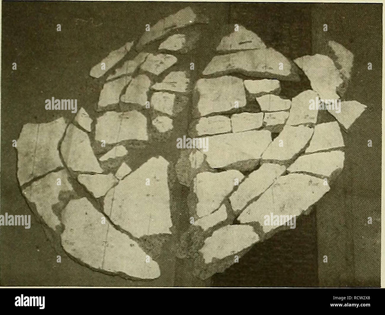 . Design for implosion of concrete cylinder structures under hydrostatic loading. Underwater concrete construction; Hydraulic structures. Figure B-14. Fragments of failure hole from specimen 3-1. For simple-support specimens, the ideal 4) of zero was not obtained. The radial deflection of the steel stiffener provided some compliance. The stiffener deflection was calculated to be about 0.01 inch (0.3 mm) at a pressure load of 500 psi (3.5 MPa), or a 4) of 0.08. Measured radial deflections showed values about 0.02 inch (0.5 mm), a )///// "°'^ ^ %^ 120 J /^J^ ^ y- 100 80 —- 7 J- 60 Stock Photohttps://www.alamy.com/image-license-details/?v=1https://www.alamy.com/design-for-implosion-of-concrete-cylinder-structures-under-hydrostatic-loading-underwater-concrete-construction-hydraulic-structures-figure-b-14-fragments-of-failure-hole-from-specimen-3-1-for-simple-support-specimens-the-ideal-4-of-zero-was-not-obtained-the-radial-deflection-of-the-steel-stiffener-provided-some-compliance-the-stiffener-deflection-was-calculated-to-be-about-001-inch-03-mm-at-a-pressure-load-of-500-psi-35-mpa-or-a-4-of-008-measured-radial-deflections-showed-values-about-002-inch-05-mm-a-quot-120-j-j-y-100-80-7-j-60-image231661760.html
RMRCW2X8–. Design for implosion of concrete cylinder structures under hydrostatic loading. Underwater concrete construction; Hydraulic structures. Figure B-14. Fragments of failure hole from specimen 3-1. For simple-support specimens, the ideal 4) of zero was not obtained. The radial deflection of the steel stiffener provided some compliance. The stiffener deflection was calculated to be about 0.01 inch (0.3 mm) at a pressure load of 500 psi (3.5 MPa), or a 4) of 0.08. Measured radial deflections showed values about 0.02 inch (0.5 mm), a )///// "°'^ ^ %^ 120 J /^J^ ^ y- 100 80 —- 7 J- 60
 . Design for implosion of concrete cylinder structures under hydrostatic loading. Underwater concrete construction; Hydraulic structures. The known terms are w, w , and AR.. Hence, radial displacements due m 1 '^ to bending can be calculated as: w + AR. - w (B-3) An estimate of the magnitude of strain on the inside and outside wall surfaces can be made because w and w, are now known. Mem- m b brane strain is calculated from: (B-4) and bending strain is calculated from an expression developed in Reference 19 as: ^ 2 r2 (B-5). 0.05 0.10 0.15 0.20 Radial Displacements, w (in.) Figure B-25. Radial Stock Photohttps://www.alamy.com/image-license-details/?v=1https://www.alamy.com/design-for-implosion-of-concrete-cylinder-structures-under-hydrostatic-loading-underwater-concrete-construction-hydraulic-structures-the-known-terms-are-w-w-and-ar-hence-radial-displacements-due-m-1-to-bending-can-be-calculated-as-w-ar-w-b-3-an-estimate-of-the-magnitude-of-strain-on-the-inside-and-outside-wall-surfaces-can-be-made-because-w-and-w-are-now-known-mem-m-b-brane-strain-is-calculated-from-b-4-and-bending-strain-is-calculated-from-an-expression-developed-in-reference-19-as-2-r2-b-5-005-010-015-020-radial-displacements-w-in-figure-b-25-radial-image215986461.html
RMPFB0X5–. Design for implosion of concrete cylinder structures under hydrostatic loading. Underwater concrete construction; Hydraulic structures. The known terms are w, w , and AR.. Hence, radial displacements due m 1 '^ to bending can be calculated as: w + AR. - w (B-3) An estimate of the magnitude of strain on the inside and outside wall surfaces can be made because w and w, are now known. Mem- m b brane strain is calculated from: (B-4) and bending strain is calculated from an expression developed in Reference 19 as: ^ 2 r2 (B-5). 0.05 0.10 0.15 0.20 Radial Displacements, w (in.) Figure B-25. Radial
 . Design for implosion of concrete cylinder structures under hydrostatic loading. Underwater concrete construction; Hydraulic structures. -1,200 -1,600 STRAIN (Min./in.) Figure A-3. Stress-strain curves from 3.25-in. diam x 6-in. long cores. TEST RESULTS Long-Term Test at 600 Feet Strain Behavior. The initial strain response of the structure on being lowered to 600 feet (180 m) showed an average strain of 380 |jin./in. in the hoop direction and 170 |jin./in. in the axial direction (Ref 9). From previous work (Refs 2, 3 and 4), it was anticipated that this low level of loading should not have p Stock Photohttps://www.alamy.com/image-license-details/?v=1https://www.alamy.com/design-for-implosion-of-concrete-cylinder-structures-under-hydrostatic-loading-underwater-concrete-construction-hydraulic-structures-1200-1600-strain-minin-figure-a-3-stress-strain-curves-from-325-in-diam-x-6-in-long-cores-test-results-long-term-test-at-600-feet-strain-behavior-the-initial-strain-response-of-the-structure-on-being-lowered-to-600-feet-180-m-showed-an-average-strain-of-380-jinin-in-the-hoop-direction-and-170-jinin-in-the-axial-direction-ref-9-from-previous-work-refs-2-3-and-4-it-was-anticipated-that-this-low-level-of-loading-should-not-have-p-image231661852.html
RMRCW31G–. Design for implosion of concrete cylinder structures under hydrostatic loading. Underwater concrete construction; Hydraulic structures. -1,200 -1,600 STRAIN (Min./in.) Figure A-3. Stress-strain curves from 3.25-in. diam x 6-in. long cores. TEST RESULTS Long-Term Test at 600 Feet Strain Behavior. The initial strain response of the structure on being lowered to 600 feet (180 m) showed an average strain of 380 |jin./in. in the hoop direction and 170 |jin./in. in the axial direction (Ref 9). From previous work (Refs 2, 3 and 4), it was anticipated that this low level of loading should not have p
 . Design for implosion of concrete cylinder structures under hydrostatic loading. Underwater concrete construction; Hydraulic structures. Figure B-8. Post-implosion view of specimen 1-1 (t/D^ = 0.024, sim- ple support). Figure B-9. Fragments of failure hole from specimen 1-1.. Figure B-10. Post-implosion view of specimen 2-1 (t/D^ = 0.037, free support). Figure B-11. Post-implosion view of specimen 2-2 (t/D^ = 0.037, free support). 59. Please note that these images are extracted from scanned page images that may have been digitally enhanced for readability - coloration and appearance of these Stock Photohttps://www.alamy.com/image-license-details/?v=1https://www.alamy.com/design-for-implosion-of-concrete-cylinder-structures-under-hydrostatic-loading-underwater-concrete-construction-hydraulic-structures-figure-b-8-post-implosion-view-of-specimen-1-1-td-=-0024-sim-ple-support-figure-b-9-fragments-of-failure-hole-from-specimen-1-1-figure-b-10-post-implosion-view-of-specimen-2-1-td-=-0037-free-support-figure-b-11-post-implosion-view-of-specimen-2-2-td-=-0037-free-support-59-please-note-that-these-images-are-extracted-from-scanned-page-images-that-may-have-been-digitally-enhanced-for-readability-coloration-and-appearance-of-these-image215986521.html
RMPFB109–. Design for implosion of concrete cylinder structures under hydrostatic loading. Underwater concrete construction; Hydraulic structures. Figure B-8. Post-implosion view of specimen 1-1 (t/D^ = 0.024, sim- ple support). Figure B-9. Fragments of failure hole from specimen 1-1.. Figure B-10. Post-implosion view of specimen 2-1 (t/D^ = 0.037, free support). Figure B-11. Post-implosion view of specimen 2-2 (t/D^ = 0.037, free support). 59. Please note that these images are extracted from scanned page images that may have been digitally enhanced for readability - coloration and appearance of these
 . Design for implosion of concrete cylinder structures under hydrostatic loading. Underwater concrete construction; Hydraulic structures. Figure B-8. Post-implosion view of specimen 1-1 (t/D^ = 0.024, sim- ple support). Figure B-9. Fragments of failure hole from specimen 1-1.. Figure B-10. Post-implosion view of specimen 2-1 (t/D^ = 0.037, free support). Figure B-11. Post-implosion view of specimen 2-2 (t/D^ = 0.037, free support). 59. Please note that these images are extracted from scanned page images that may have been digitally enhanced for readability - coloration and appearance of these Stock Photohttps://www.alamy.com/image-license-details/?v=1https://www.alamy.com/design-for-implosion-of-concrete-cylinder-structures-under-hydrostatic-loading-underwater-concrete-construction-hydraulic-structures-figure-b-8-post-implosion-view-of-specimen-1-1-td-=-0024-sim-ple-support-figure-b-9-fragments-of-failure-hole-from-specimen-1-1-figure-b-10-post-implosion-view-of-specimen-2-1-td-=-0037-free-support-figure-b-11-post-implosion-view-of-specimen-2-2-td-=-0037-free-support-59-please-note-that-these-images-are-extracted-from-scanned-page-images-that-may-have-been-digitally-enhanced-for-readability-coloration-and-appearance-of-these-image231661785.html
RMRCW2Y5–. Design for implosion of concrete cylinder structures under hydrostatic loading. Underwater concrete construction; Hydraulic structures. Figure B-8. Post-implosion view of specimen 1-1 (t/D^ = 0.024, sim- ple support). Figure B-9. Fragments of failure hole from specimen 1-1.. Figure B-10. Post-implosion view of specimen 2-1 (t/D^ = 0.037, free support). Figure B-11. Post-implosion view of specimen 2-2 (t/D^ = 0.037, free support). 59. Please note that these images are extracted from scanned page images that may have been digitally enhanced for readability - coloration and appearance of these
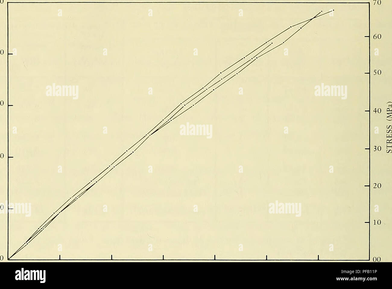 . Design for implosion of concrete cylinder structures under hydrostatic loading. Underwater concrete construction; Hydraulic structures. -1,200 -1,600 STRAIN (Min./in.) Figure A-3. Stress-strain curves from 3.25-in. diam x 6-in. long cores. TEST RESULTS Long-Term Test at 600 Feet Strain Behavior. The initial strain response of the structure on being lowered to 600 feet (180 m) showed an average strain of 380 |jin./in. in the hoop direction and 170 |jin./in. in the axial direction (Ref 9). From previous work (Refs 2, 3 and 4), it was anticipated that this low level of loading should not have p Stock Photohttps://www.alamy.com/image-license-details/?v=1https://www.alamy.com/design-for-implosion-of-concrete-cylinder-structures-under-hydrostatic-loading-underwater-concrete-construction-hydraulic-structures-1200-1600-strain-minin-figure-a-3-stress-strain-curves-from-325-in-diam-x-6-in-long-cores-test-results-long-term-test-at-600-feet-strain-behavior-the-initial-strain-response-of-the-structure-on-being-lowered-to-600-feet-180-m-showed-an-average-strain-of-380-jinin-in-the-hoop-direction-and-170-jinin-in-the-axial-direction-ref-9-from-previous-work-refs-2-3-and-4-it-was-anticipated-that-this-low-level-of-loading-should-not-have-p-image215986562.html
RMPFB11P–. Design for implosion of concrete cylinder structures under hydrostatic loading. Underwater concrete construction; Hydraulic structures. -1,200 -1,600 STRAIN (Min./in.) Figure A-3. Stress-strain curves from 3.25-in. diam x 6-in. long cores. TEST RESULTS Long-Term Test at 600 Feet Strain Behavior. The initial strain response of the structure on being lowered to 600 feet (180 m) showed an average strain of 380 |jin./in. in the hoop direction and 170 |jin./in. in the axial direction (Ref 9). From previous work (Refs 2, 3 and 4), it was anticipated that this low level of loading should not have p
 . Design for implosion of concrete cylinder structures under hydrostatic loading. Underwater concrete construction; Hydraulic structures. The known terms are w, w , and AR.. Hence, radial displacements due m 1 '^ to bending can be calculated as: w + AR. - w (B-3) An estimate of the magnitude of strain on the inside and outside wall surfaces can be made because w and w, are now known. Mem- m b brane strain is calculated from: (B-4) and bending strain is calculated from an expression developed in Reference 19 as: ^ 2 r2 (B-5). 0.05 0.10 0.15 0.20 Radial Displacements, w (in.) Figure B-25. Radial Stock Photohttps://www.alamy.com/image-license-details/?v=1https://www.alamy.com/design-for-implosion-of-concrete-cylinder-structures-under-hydrostatic-loading-underwater-concrete-construction-hydraulic-structures-the-known-terms-are-w-w-and-ar-hence-radial-displacements-due-m-1-to-bending-can-be-calculated-as-w-ar-w-b-3-an-estimate-of-the-magnitude-of-strain-on-the-inside-and-outside-wall-surfaces-can-be-made-because-w-and-w-are-now-known-mem-m-b-brane-strain-is-calculated-from-b-4-and-bending-strain-is-calculated-from-an-expression-developed-in-reference-19-as-2-r2-b-5-005-010-015-020-radial-displacements-w-in-figure-b-25-radial-image231661692.html
RMRCW2RT–. Design for implosion of concrete cylinder structures under hydrostatic loading. Underwater concrete construction; Hydraulic structures. The known terms are w, w , and AR.. Hence, radial displacements due m 1 '^ to bending can be calculated as: w + AR. - w (B-3) An estimate of the magnitude of strain on the inside and outside wall surfaces can be made because w and w, are now known. Mem- m b brane strain is calculated from: (B-4) and bending strain is calculated from an expression developed in Reference 19 as: ^ 2 r2 (B-5). 0.05 0.10 0.15 0.20 Radial Displacements, w (in.) Figure B-25. Radial
 . Design for implosion of concrete cylinder structures under hydrostatic loading. Underwater concrete construction; Hydraulic structures. t/Dp = 0.037 L/Dj,= 2,35 simple support t = 1.97 in. 0.10 Radial Displacements, w (in.) Figure B-22. Radial displacement behavior at midlength of Group 3 cylinders having t/D = 0.037 and simple support.. 0.10 0.15 0.20 Radial Displacements, w (in.) Figure B-23. Radial displacement behavior along length of specimen 1-1 having t/D = 0.024 and simple support at a pressure load of 0.89 P- . ff 1^ -*'W experimental (one specimen) analytical H t= 1.97 in. t/Do - Stock Photohttps://www.alamy.com/image-license-details/?v=1https://www.alamy.com/design-for-implosion-of-concrete-cylinder-structures-under-hydrostatic-loading-underwater-concrete-construction-hydraulic-structures-tdp-=-0037-ldj=-235-simple-support-t-=-197-in-010-radial-displacements-w-in-figure-b-22-radial-displacement-behavior-at-midlength-of-group-3-cylinders-having-td-=-0037-and-simple-support-010-015-020-radial-displacements-w-in-figure-b-23-radial-displacement-behavior-along-length-of-specimen-1-1-having-td-=-0024-and-simple-support-at-a-pressure-load-of-089-p-ff-1-w-experimental-one-specimen-analytical-h-t=-197-in-tdo-image215986468.html
RMPFB0XC–. Design for implosion of concrete cylinder structures under hydrostatic loading. Underwater concrete construction; Hydraulic structures. t/Dp = 0.037 L/Dj,= 2,35 simple support t = 1.97 in. 0.10 Radial Displacements, w (in.) Figure B-22. Radial displacement behavior at midlength of Group 3 cylinders having t/D = 0.037 and simple support.. 0.10 0.15 0.20 Radial Displacements, w (in.) Figure B-23. Radial displacement behavior along length of specimen 1-1 having t/D = 0.024 and simple support at a pressure load of 0.89 P- . ff 1^ -*'W experimental (one specimen) analytical H t= 1.97 in. t/Do -
 . Design for implosion of concrete cylinder structures under hydrostatic loading. Underwater concrete construction; Hydraulic structures. 7 400 - t/Dg = 0.024 stress L/D^=2.35 control failure simple support ja. :'-; w j perfect cylinder, Case 1 /^ Y /⢠â >- strain control Arm LJ^ I t = 1.31 in.. out-of-round cylinder, Case 2 instability failure experimental (one specimen) â ^â analytical 0.05 0.10 0,15 Radial Displacements, w (in.) Figure B-20. Radial displacement behavior at midlength of specimen 1-1 having t/D = 0.024 and simple support. 1 â Rq = 27 in.- -1 1 700 T.I 'i w 1 t/Dg Stock Photohttps://www.alamy.com/image-license-details/?v=1https://www.alamy.com/design-for-implosion-of-concrete-cylinder-structures-under-hydrostatic-loading-underwater-concrete-construction-hydraulic-structures-7-400-tdg-=-0024-stress-ld=235-control-failure-simple-support-ja-w-j-perfect-cylinder-case-1-y-gt-strain-control-arm-lj-i-t-=-131-in-out-of-round-cylinder-case-2-instability-failure-experimental-one-specimen-analytical-005-010-015-radial-displacements-w-in-figure-b-20-radial-displacement-behavior-at-midlength-of-specimen-1-1-having-td-=-0024-and-simple-support-1-rq-=-27-in-1-1-700-ti-i-w-1-tdg-image231661722.html
RMRCW2TX–. Design for implosion of concrete cylinder structures under hydrostatic loading. Underwater concrete construction; Hydraulic structures. 7 400 - t/Dg = 0.024 stress L/D^=2.35 control failure simple support ja. :'-; w j perfect cylinder, Case 1 /^ Y /⢠â >- strain control Arm LJ^ I t = 1.31 in.. out-of-round cylinder, Case 2 instability failure experimental (one specimen) â ^â analytical 0.05 0.10 0,15 Radial Displacements, w (in.) Figure B-20. Radial displacement behavior at midlength of specimen 1-1 having t/D = 0.024 and simple support. 1 â Rq = 27 in.- -1 1 700 T.I 'i w 1 t/Dg
 . Design for implosion of concrete cylinder structures under hydrostatic loading. Underwater concrete construction; Hydraulic structures. 7 400 - t/Dg = 0.024 stress L/D^=2.35 control failure simple support ja. :'-; w j perfect cylinder, Case 1 /^ Y /⢠â >- strain control Arm LJ^ I t = 1.31 in.. out-of-round cylinder, Case 2 instability failure experimental (one specimen) â ^â analytical 0.05 0.10 0,15 Radial Displacements, w (in.) Figure B-20. Radial displacement behavior at midlength of specimen 1-1 having t/D = 0.024 and simple support. 1 â Rq = 27 in.- -1 1 700 T.I 'i w 1 t/Dg Stock Photohttps://www.alamy.com/image-license-details/?v=1https://www.alamy.com/design-for-implosion-of-concrete-cylinder-structures-under-hydrostatic-loading-underwater-concrete-construction-hydraulic-structures-7-400-tdg-=-0024-stress-ld=235-control-failure-simple-support-ja-w-j-perfect-cylinder-case-1-y-gt-strain-control-arm-lj-i-t-=-131-in-out-of-round-cylinder-case-2-instability-failure-experimental-one-specimen-analytical-005-010-015-radial-displacements-w-in-figure-b-20-radial-displacement-behavior-at-midlength-of-specimen-1-1-having-td-=-0024-and-simple-support-1-rq-=-27-in-1-1-700-ti-i-w-1-tdg-image215986481.html
RMPFB0XW–. Design for implosion of concrete cylinder structures under hydrostatic loading. Underwater concrete construction; Hydraulic structures. 7 400 - t/Dg = 0.024 stress L/D^=2.35 control failure simple support ja. :'-; w j perfect cylinder, Case 1 /^ Y /⢠â >- strain control Arm LJ^ I t = 1.31 in.. out-of-round cylinder, Case 2 instability failure experimental (one specimen) â ^â analytical 0.05 0.10 0,15 Radial Displacements, w (in.) Figure B-20. Radial displacement behavior at midlength of specimen 1-1 having t/D = 0.024 and simple support. 1 â Rq = 27 in.- -1 1 700 T.I 'i w 1 t/Dg
 . Design for implosion of concrete cylinder structures under hydrostatic loading. Underwater concrete construction; Hydraulic structures. t/Dp = 0.037 L/Dj,= 2,35 simple support t = 1.97 in. 0.10 Radial Displacements, w (in.) Figure B-22. Radial displacement behavior at midlength of Group 3 cylinders having t/D = 0.037 and simple support.. 0.10 0.15 0.20 Radial Displacements, w (in.) Figure B-23. Radial displacement behavior along length of specimen 1-1 having t/D = 0.024 and simple support at a pressure load of 0.89 P- . ff 1^ -*'W experimental (one specimen) analytical H t= 1.97 in. t/Do - Stock Photohttps://www.alamy.com/image-license-details/?v=1https://www.alamy.com/design-for-implosion-of-concrete-cylinder-structures-under-hydrostatic-loading-underwater-concrete-construction-hydraulic-structures-tdp-=-0037-ldj=-235-simple-support-t-=-197-in-010-radial-displacements-w-in-figure-b-22-radial-displacement-behavior-at-midlength-of-group-3-cylinders-having-td-=-0037-and-simple-support-010-015-020-radial-displacements-w-in-figure-b-23-radial-displacement-behavior-along-length-of-specimen-1-1-having-td-=-0024-and-simple-support-at-a-pressure-load-of-089-p-ff-1-w-experimental-one-specimen-analytical-h-t=-197-in-tdo-image231661700.html
RMRCW2T4–. Design for implosion of concrete cylinder structures under hydrostatic loading. Underwater concrete construction; Hydraulic structures. t/Dp = 0.037 L/Dj,= 2,35 simple support t = 1.97 in. 0.10 Radial Displacements, w (in.) Figure B-22. Radial displacement behavior at midlength of Group 3 cylinders having t/D = 0.037 and simple support.. 0.10 0.15 0.20 Radial Displacements, w (in.) Figure B-23. Radial displacement behavior along length of specimen 1-1 having t/D = 0.024 and simple support at a pressure load of 0.89 P- . ff 1^ -*'W experimental (one specimen) analytical H t= 1.97 in. t/Do -