Quick filters:
Two way switch circuit Stock Photos and Images
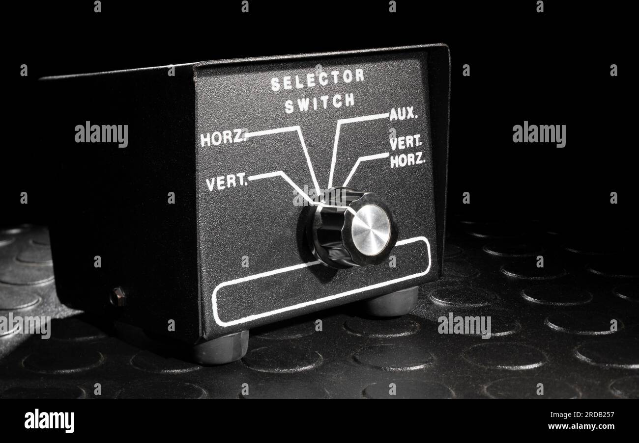 Switch to change which antenna is connected to a two-way radio Stock Photohttps://www.alamy.com/image-license-details/?v=1https://www.alamy.com/switch-to-change-which-antenna-is-connected-to-a-two-way-radio-image558965491.html
RF2RDB257–Switch to change which antenna is connected to a two-way radio
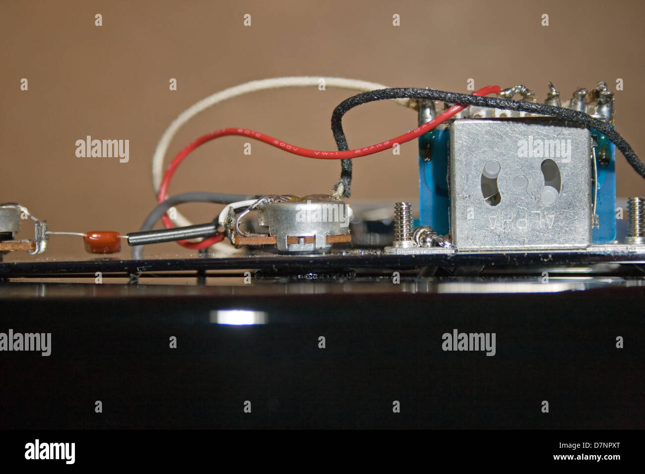 Electrical components inside a telecaster type guitar. Stock Photohttps://www.alamy.com/image-license-details/?v=1https://www.alamy.com/stock-photo-electrical-components-inside-a-telecaster-type-guitar-56412688.html
RMD7NPXT–Electrical components inside a telecaster type guitar.
 Electrcal Symbols Short Set 048 Single Pole Double Throw Two Way Changeover Switch Stock Photohttps://www.alamy.com/image-license-details/?v=1https://www.alamy.com/electrcal-symbols-short-set-048-single-pole-double-throw-two-way-changeover-switch-image397615464.html
RM2E2TXG8–Electrcal Symbols Short Set 048 Single Pole Double Throw Two Way Changeover Switch
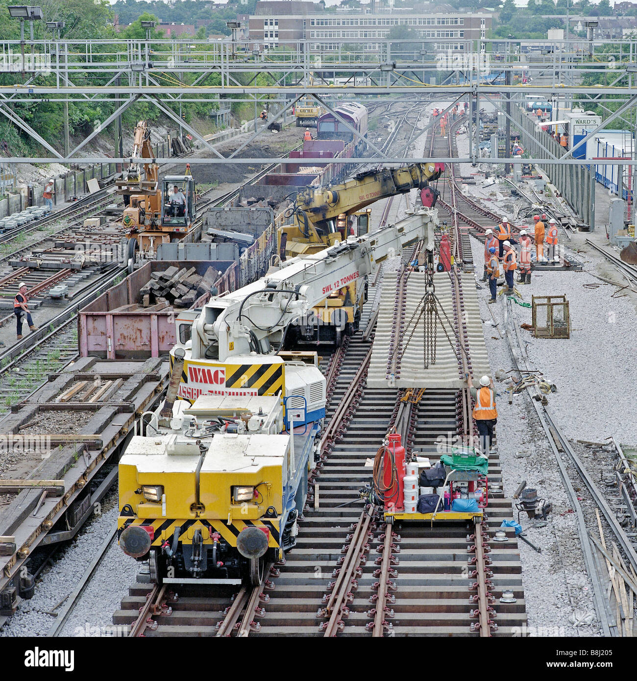 Tandem lift by two self-propelled rail cranes of a heavy prefabricated track panel during a major railway upgrading programme. Stock Photohttps://www.alamy.com/image-license-details/?v=1https://www.alamy.com/stock-photo-tandem-lift-by-two-self-propelled-rail-cranes-of-a-heavy-prefabricated-22524325.html
RMB8J205–Tandem lift by two self-propelled rail cranes of a heavy prefabricated track panel during a major railway upgrading programme.
 . American engineer and railroad journal . anel contains themain field switch and rheostat handwheel, together with an elec-tric governor controller for changing the speed of the generatorsfrom the switchboard gallery for the purpose of synchronizing,when it is desired to throw two or more generators in parallel.The oil circuit breakers between the generator and the buses arealso electrically controlled from these panels. Totalizing watt-meters are placed in the bus sections in such a way as to registerthe total load of the generators or of any group of feeders. Each feeder is equipped with an Stock Photohttps://www.alamy.com/image-license-details/?v=1https://www.alamy.com/american-engineer-and-railroad-journal-anel-contains-themain-field-switch-and-rheostat-handwheel-together-with-an-elec-tric-governor-controller-for-changing-the-speed-of-the-generatorsfrom-the-switchboard-gallery-for-the-purpose-of-synchronizingwhen-it-is-desired-to-throw-two-or-more-generators-in-parallelthe-oil-circuit-breakers-between-the-generator-and-the-buses-arealso-electrically-controlled-from-these-panels-totalizing-watt-meters-are-placed-in-the-bus-sections-in-such-a-way-as-to-registerthe-total-load-of-the-generators-or-of-any-group-of-feeders-each-feeder-is-equipped-with-an-image375802086.html
RM2CRB7B2–. American engineer and railroad journal . anel contains themain field switch and rheostat handwheel, together with an elec-tric governor controller for changing the speed of the generatorsfrom the switchboard gallery for the purpose of synchronizing,when it is desired to throw two or more generators in parallel.The oil circuit breakers between the generator and the buses arealso electrically controlled from these panels. Totalizing watt-meters are placed in the bus sections in such a way as to registerthe total load of the generators or of any group of feeders. Each feeder is equipped with an
 Switch that allows changing between vertical and horizontal antennas on a two-way radio Stock Photohttps://www.alamy.com/image-license-details/?v=1https://www.alamy.com/switch-that-allows-changing-between-vertical-and-horizontal-antennas-on-a-two-way-radio-image557576895.html
RF2RB3R0F–Switch that allows changing between vertical and horizontal antennas on a two-way radio
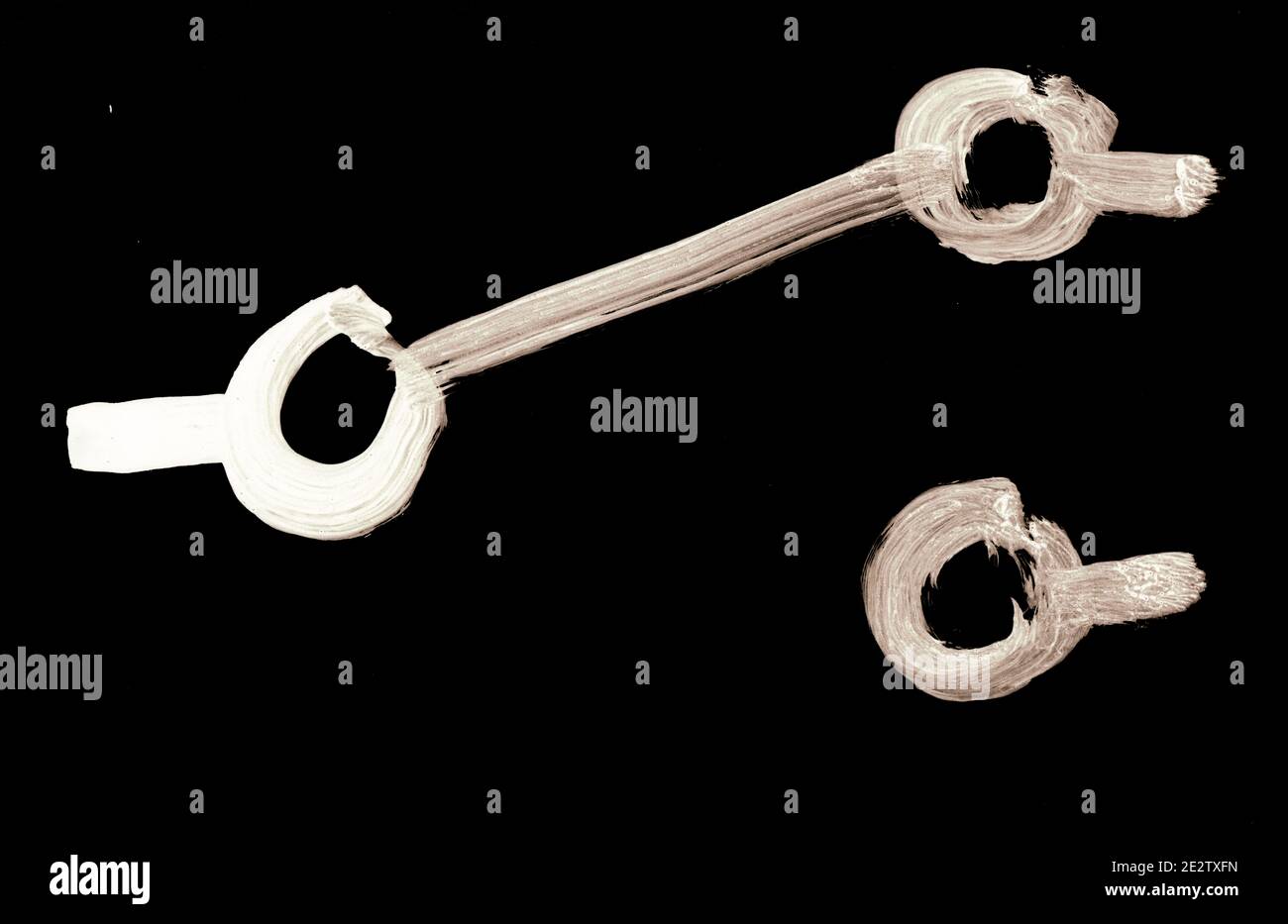 Electrcal Symbols Short Set 048 Single Pole Double Throw Two Way Changeover Switch Inverted Stock Photohttps://www.alamy.com/image-license-details/?v=1https://www.alamy.com/electrcal-symbols-short-set-048-single-pole-double-throw-two-way-changeover-switch-inverted-image397615449.html
RM2E2TXFN–Electrcal Symbols Short Set 048 Single Pole Double Throw Two Way Changeover Switch Inverted
 . The Bell System technical journal . ,one for each of the two circuits compared, which are adjusted beforethe test begins and are then controlled by the master switch. Quickchange from one magnitude of line noise to another is managed in thesame way. Likewise, the setting of the automatic volume indicatorin the callers control circuit is under the control of the master switchso that different calling intensities can be used on successive conditions.Before each list is called the operation of the switching apparatusand the circuit elements are checked rapidly at the control board bythe applica Stock Photohttps://www.alamy.com/image-license-details/?v=1https://www.alamy.com/the-bell-system-technical-journal-one-for-each-of-the-two-circuits-compared-which-are-adjusted-beforethe-test-begins-and-are-then-controlled-by-the-master-switch-quickchange-from-one-magnitude-of-line-noise-to-another-is-managed-in-thesame-way-likewise-the-setting-of-the-automatic-volume-indicatorin-the-callers-control-circuit-is-under-the-control-of-the-master-switchso-that-different-calling-intensities-can-be-used-on-successive-conditionsbefore-each-list-is-called-the-operation-of-the-switching-apparatusand-the-circuit-elements-are-checked-rapidly-at-the-control-board-bythe-applica-image376111857.html
RM2CRWAE9–. The Bell System technical journal . ,one for each of the two circuits compared, which are adjusted beforethe test begins and are then controlled by the master switch. Quickchange from one magnitude of line noise to another is managed in thesame way. Likewise, the setting of the automatic volume indicatorin the callers control circuit is under the control of the master switchso that different calling intensities can be used on successive conditions.Before each list is called the operation of the switching apparatusand the circuit elements are checked rapidly at the control board bythe applica
 Four SO-239 connections at the back of an antenna swircher used for two-way radios Stock Photohttps://www.alamy.com/image-license-details/?v=1https://www.alamy.com/four-so-239-connections-at-the-back-of-an-antenna-swircher-used-for-two-way-radios-image599105708.html
RF2WPKHCC–Four SO-239 connections at the back of an antenna swircher used for two-way radios
 . The Street railway journal . oss connected in the same way with operating head, two motormens multiple control switches,one railway type circuit-breaker, one set of connectors, a smallstorage battery and an auxiliary air reservoir. The controlleris of the series-parallel type and is similar in design to the ordinaryform of hand controller which has been in successful use formany years. A multiple control switch is placed at one or bothends of each motor-car and by means of the one at the front of theleading car the motorman directs the action of the controllers onall the motor-cars in the tr Stock Photohttps://www.alamy.com/image-license-details/?v=1https://www.alamy.com/the-street-railway-journal-oss-connected-in-the-same-way-with-operating-head-two-motormens-multiple-control-switchesone-railway-type-circuit-breaker-one-set-of-connectors-a-smallstorage-battery-and-an-auxiliary-air-reservoir-the-controlleris-of-the-series-parallel-type-and-is-similar-in-design-to-the-ordinaryform-of-hand-controller-which-has-been-in-successful-use-formany-years-a-multiple-control-switch-is-placed-at-one-or-bothends-of-each-motor-car-and-by-means-of-the-one-at-the-front-of-theleading-car-the-motorman-directs-the-action-of-the-controllers-onall-the-motor-cars-in-the-tr-image371820636.html
RM2CGWW0C–. The Street railway journal . oss connected in the same way with operating head, two motormens multiple control switches,one railway type circuit-breaker, one set of connectors, a smallstorage battery and an auxiliary air reservoir. The controlleris of the series-parallel type and is similar in design to the ordinaryform of hand controller which has been in successful use formany years. A multiple control switch is placed at one or bothends of each motor-car and by means of the one at the front of theleading car the motorman directs the action of the controllers onall the motor-cars in the tr
 Plugs for connecting the coax on two-way radios on the back of an antenna selector Stock Photohttps://www.alamy.com/image-license-details/?v=1https://www.alamy.com/plugs-for-connecting-the-coax-on-two-way-radios-on-the-back-of-an-antenna-selector-image566225637.html
RF2RW5PG5–Plugs for connecting the coax on two-way radios on the back of an antenna selector
![. Electric railway journal . rmen now go through the instruction course, theywill not only become familiar with the very latest form ofbraking and draft-rigging equipments in use but will also havethe opportunity of studying the electrical operation of trains in former control can be used in the actual running of the car,as a two-way switch permits the instruction board1 circuit tobe cut in or out as the case may be. Each control systemhas all of its components mounted inside the car in plain view February 5, 1910.] ELECTRIC RAILWAY JOURNAL. 221 and is supplemented by sections of the principal Stock Photo . Electric railway journal . rmen now go through the instruction course, theywill not only become familiar with the very latest form ofbraking and draft-rigging equipments in use but will also havethe opportunity of studying the electrical operation of trains in former control can be used in the actual running of the car,as a two-way switch permits the instruction board1 circuit tobe cut in or out as the case may be. Each control systemhas all of its components mounted inside the car in plain view February 5, 1910.] ELECTRIC RAILWAY JOURNAL. 221 and is supplemented by sections of the principal Stock Photo](https://c8.alamy.com/comp/2CH3PBE/electric-railway-journal-rmen-now-go-through-the-instruction-course-theywill-not-only-become-familiar-with-the-very-latest-form-ofbraking-and-draft-rigging-equipments-in-use-but-will-also-havethe-opportunity-of-studying-the-electrical-operation-of-trains-in-former-control-can-be-used-in-the-actual-running-of-the-caras-a-two-way-switch-permits-the-instruction-board1-circuit-tobe-cut-in-or-out-as-the-case-may-be-each-control-systemhas-all-of-its-components-mounted-inside-the-car-in-plain-view-february-5-1910-electric-railway-journal-221-and-is-supplemented-by-sections-of-the-principal-2CH3PBE.jpg) . Electric railway journal . rmen now go through the instruction course, theywill not only become familiar with the very latest form ofbraking and draft-rigging equipments in use but will also havethe opportunity of studying the electrical operation of trains in former control can be used in the actual running of the car,as a two-way switch permits the instruction board1 circuit tobe cut in or out as the case may be. Each control systemhas all of its components mounted inside the car in plain view February 5, 1910.] ELECTRIC RAILWAY JOURNAL. 221 and is supplemented by sections of the principal Stock Photohttps://www.alamy.com/image-license-details/?v=1https://www.alamy.com/electric-railway-journal-rmen-now-go-through-the-instruction-course-theywill-not-only-become-familiar-with-the-very-latest-form-ofbraking-and-draft-rigging-equipments-in-use-but-will-also-havethe-opportunity-of-studying-the-electrical-operation-of-trains-in-former-control-can-be-used-in-the-actual-running-of-the-caras-a-two-way-switch-permits-the-instruction-board1-circuit-tobe-cut-in-or-out-as-the-case-may-be-each-control-systemhas-all-of-its-components-mounted-inside-the-car-in-plain-view-february-5-1910-electric-railway-journal-221-and-is-supplemented-by-sections-of-the-principal-image371950306.html
. Electric railway journal . rmen now go through the instruction course, theywill not only become familiar with the very latest form ofbraking and draft-rigging equipments in use but will also havethe opportunity of studying the electrical operation of trains in former control can be used in the actual running of the car,as a two-way switch permits the instruction board1 circuit tobe cut in or out as the case may be. Each control systemhas all of its components mounted inside the car in plain view February 5, 1910.] ELECTRIC RAILWAY JOURNAL. 221 and is supplemented by sections of the principal Stock Photohttps://www.alamy.com/image-license-details/?v=1https://www.alamy.com/electric-railway-journal-rmen-now-go-through-the-instruction-course-theywill-not-only-become-familiar-with-the-very-latest-form-ofbraking-and-draft-rigging-equipments-in-use-but-will-also-havethe-opportunity-of-studying-the-electrical-operation-of-trains-in-former-control-can-be-used-in-the-actual-running-of-the-caras-a-two-way-switch-permits-the-instruction-board1-circuit-tobe-cut-in-or-out-as-the-case-may-be-each-control-systemhas-all-of-its-components-mounted-inside-the-car-in-plain-view-february-5-1910-electric-railway-journal-221-and-is-supplemented-by-sections-of-the-principal-image371950306.htmlRM2CH3PBE–. Electric railway journal . rmen now go through the instruction course, theywill not only become familiar with the very latest form ofbraking and draft-rigging equipments in use but will also havethe opportunity of studying the electrical operation of trains in former control can be used in the actual running of the car,as a two-way switch permits the instruction board1 circuit tobe cut in or out as the case may be. Each control systemhas all of its components mounted inside the car in plain view February 5, 1910.] ELECTRIC RAILWAY JOURNAL. 221 and is supplemented by sections of the principal
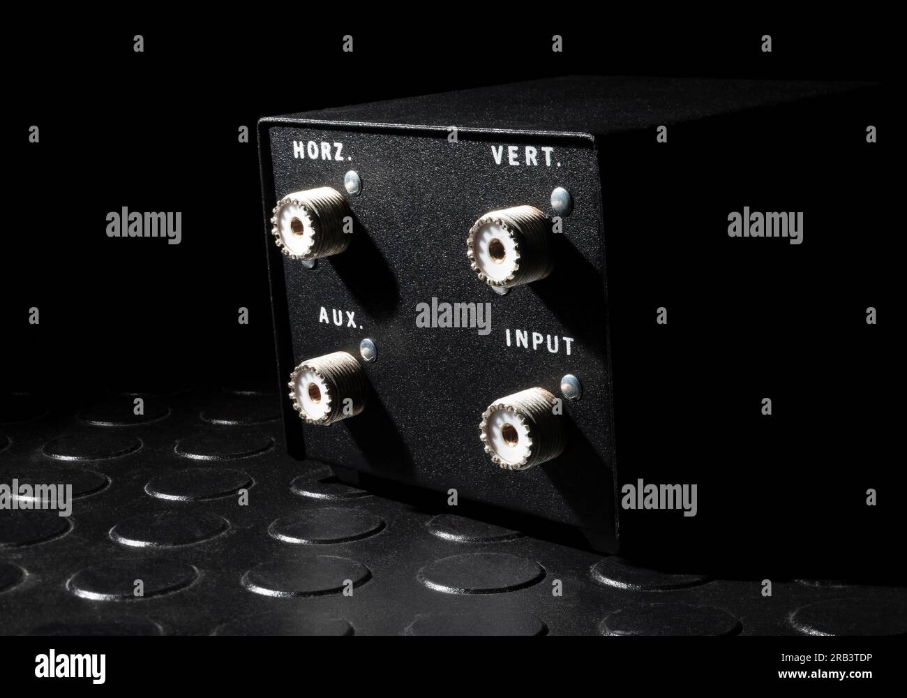 Antenna switcher for two-way radios seen from the rear with four SO-239 connections for coax Stock Photohttps://www.alamy.com/image-license-details/?v=1https://www.alamy.com/antenna-switcher-for-two-way-radios-seen-from-the-rear-with-four-so-239-connections-for-coax-image557578050.html
RF2RB3TDP–Antenna switcher for two-way radios seen from the rear with four SO-239 connections for coax
 . The Street railway journal . o 500 ft long. They have No. 10frogs and spring switches, and under the operating rules theeast end of every switch is locked open, so that every west-bound car takes the siding and eastbound cars the main line.The trolley wire is arranged in the same way, so that it is notnecessary to change the trolley at any time. At each siding isa circuit of six no-volt lamps; two at each switch and two inthe telephone booth, and the practice is to allow them to burnall the time. Extra lamps are carried in the telephone booth. Telephone booths are placed at all sidings and w Stock Photohttps://www.alamy.com/image-license-details/?v=1https://www.alamy.com/the-street-railway-journal-o-500-ft-long-they-have-no-10frogs-and-spring-switches-and-under-the-operating-rules-theeast-end-of-every-switch-is-locked-open-so-that-every-west-bound-car-takes-the-siding-and-eastbound-cars-the-main-linethe-trolley-wire-is-arranged-in-the-same-way-so-that-it-is-notnecessary-to-change-the-trolley-at-any-time-at-each-siding-isa-circuit-of-six-no-volt-lamps-two-at-each-switch-and-two-inthe-telephone-booth-and-the-practice-is-to-allow-them-to-burnall-the-time-extra-lamps-are-carried-in-the-telephone-booth-telephone-booths-are-placed-at-all-sidings-and-w-image371912582.html
RM2CH2286–. The Street railway journal . o 500 ft long. They have No. 10frogs and spring switches, and under the operating rules theeast end of every switch is locked open, so that every west-bound car takes the siding and eastbound cars the main line.The trolley wire is arranged in the same way, so that it is notnecessary to change the trolley at any time. At each siding isa circuit of six no-volt lamps; two at each switch and two inthe telephone booth, and the practice is to allow them to burnall the time. Extra lamps are carried in the telephone booth. Telephone booths are placed at all sidings and w
![. Electric railway journal . lights, each of these circuits being in dupli-cate and governed by a two-way switch, so that there mayalways be a light in the destination indicator and signallamps in the case of failure of one circuit. The cars areheated by electric heaters, there being 16 distributedthroughout the car, all connected in series. Two heatersat each end are situated in the drivers cab. The proportion of motor cars to trailers in trains is oneto one. The weight of these motor cars in running order,but without passenger load, is 33^ tons. August 21, 1909.] ELECTRIC RAILWAY JOURNAL. 29 Stock Photo . Electric railway journal . lights, each of these circuits being in dupli-cate and governed by a two-way switch, so that there mayalways be a light in the destination indicator and signallamps in the case of failure of one circuit. The cars areheated by electric heaters, there being 16 distributedthroughout the car, all connected in series. Two heatersat each end are situated in the drivers cab. The proportion of motor cars to trailers in trains is oneto one. The weight of these motor cars in running order,but without passenger load, is 33^ tons. August 21, 1909.] ELECTRIC RAILWAY JOURNAL. 29 Stock Photo](https://c8.alamy.com/comp/2CGX24J/electric-railway-journal-lights-each-of-these-circuits-being-in-dupli-cate-and-governed-by-a-two-way-switch-so-that-there-mayalways-be-a-light-in-the-destination-indicator-and-signallamps-in-the-case-of-failure-of-one-circuit-the-cars-areheated-by-electric-heaters-there-being-16-distributedthroughout-the-car-all-connected-in-series-two-heatersat-each-end-are-situated-in-the-drivers-cab-the-proportion-of-motor-cars-to-trailers-in-trains-is-oneto-one-the-weight-of-these-motor-cars-in-running-orderbut-without-passenger-load-is-33-tons-august-21-1909-electric-railway-journal-29-2CGX24J.jpg) . Electric railway journal . lights, each of these circuits being in dupli-cate and governed by a two-way switch, so that there mayalways be a light in the destination indicator and signallamps in the case of failure of one circuit. The cars areheated by electric heaters, there being 16 distributedthroughout the car, all connected in series. Two heatersat each end are situated in the drivers cab. The proportion of motor cars to trailers in trains is oneto one. The weight of these motor cars in running order,but without passenger load, is 33^ tons. August 21, 1909.] ELECTRIC RAILWAY JOURNAL. 29 Stock Photohttps://www.alamy.com/image-license-details/?v=1https://www.alamy.com/electric-railway-journal-lights-each-of-these-circuits-being-in-dupli-cate-and-governed-by-a-two-way-switch-so-that-there-mayalways-be-a-light-in-the-destination-indicator-and-signallamps-in-the-case-of-failure-of-one-circuit-the-cars-areheated-by-electric-heaters-there-being-16-distributedthroughout-the-car-all-connected-in-series-two-heatersat-each-end-are-situated-in-the-drivers-cab-the-proportion-of-motor-cars-to-trailers-in-trains-is-oneto-one-the-weight-of-these-motor-cars-in-running-orderbut-without-passenger-load-is-33-tons-august-21-1909-electric-railway-journal-29-image371824674.html
. Electric railway journal . lights, each of these circuits being in dupli-cate and governed by a two-way switch, so that there mayalways be a light in the destination indicator and signallamps in the case of failure of one circuit. The cars areheated by electric heaters, there being 16 distributedthroughout the car, all connected in series. Two heatersat each end are situated in the drivers cab. The proportion of motor cars to trailers in trains is oneto one. The weight of these motor cars in running order,but without passenger load, is 33^ tons. August 21, 1909.] ELECTRIC RAILWAY JOURNAL. 29 Stock Photohttps://www.alamy.com/image-license-details/?v=1https://www.alamy.com/electric-railway-journal-lights-each-of-these-circuits-being-in-dupli-cate-and-governed-by-a-two-way-switch-so-that-there-mayalways-be-a-light-in-the-destination-indicator-and-signallamps-in-the-case-of-failure-of-one-circuit-the-cars-areheated-by-electric-heaters-there-being-16-distributedthroughout-the-car-all-connected-in-series-two-heatersat-each-end-are-situated-in-the-drivers-cab-the-proportion-of-motor-cars-to-trailers-in-trains-is-oneto-one-the-weight-of-these-motor-cars-in-running-orderbut-without-passenger-load-is-33-tons-august-21-1909-electric-railway-journal-29-image371824674.htmlRM2CGX24J–. Electric railway journal . lights, each of these circuits being in dupli-cate and governed by a two-way switch, so that there mayalways be a light in the destination indicator and signallamps in the case of failure of one circuit. The cars areheated by electric heaters, there being 16 distributedthroughout the car, all connected in series. Two heatersat each end are situated in the drivers cab. The proportion of motor cars to trailers in trains is oneto one. The weight of these motor cars in running order,but without passenger load, is 33^ tons. August 21, 1909.] ELECTRIC RAILWAY JOURNAL. 29
 . The street railway review . istance fitted with a carbon breakand also a circuit connecting piece. The battery current is controlled by two hand regulators, a bat-tery switch and a battery change-over switch, the latter serving toconnect the two halves of the battery in series or in parallel. The ra •• ••1 ^ 1 HCi^L^^^^Hl^ .^^^1 CONVEkXEK STATION. iiistruiiKiUs used with the battery are an ammeter, a voltmeter anda niulliple way voltmeter switch joined to the two halves of thebattery. The feeders as well as the leads to the trolley wires eachcontain two automatic circuit hnaker.-^, two ammet Stock Photohttps://www.alamy.com/image-license-details/?v=1https://www.alamy.com/the-street-railway-review-istance-fitted-with-a-carbon-breakand-also-a-circuit-connecting-piece-the-battery-current-is-controlled-by-two-hand-regulators-a-bat-tery-switch-and-a-battery-change-over-switch-the-latter-serving-toconnect-the-two-halves-of-the-battery-in-series-or-in-parallel-the-ra-1-1-hcilhl-1-convekxek-station-iiistruiikius-used-with-the-battery-are-an-ammeter-a-voltmeter-anda-niulliple-way-voltmeter-switch-joined-to-the-two-halves-of-thebattery-the-feeders-as-well-as-the-leads-to-the-trolley-wires-eachcontain-two-automatic-circuit-hnaker-two-ammet-image371774550.html
RM2CGRP6E–. The street railway review . istance fitted with a carbon breakand also a circuit connecting piece. The battery current is controlled by two hand regulators, a bat-tery switch and a battery change-over switch, the latter serving toconnect the two halves of the battery in series or in parallel. The ra •• ••1 ^ 1 HCi^L^^^^Hl^ .^^^1 CONVEkXEK STATION. iiistruiiKiUs used with the battery are an ammeter, a voltmeter anda niulliple way voltmeter switch joined to the two halves of thebattery. The feeders as well as the leads to the trolley wires eachcontain two automatic circuit hnaker.-^, two ammet
 . Electric railway journal . Tap to Governor. Wiring for Air Compressor.Wiring beneath Car to he In i Co Electric Ry. Journal Baltimore Prepayment Car—Compressor Circuit arranged in two boxes of 25 grids each. Fifteen-tooth specialgrade pinions are used in connection with 69-tooth solid gears.The gear cases are of sheet steel put together by the oxyacety-lene process. The cables within the car are placed in the transite-linedcable box running the length of the car. The leads of thecables running the controller, motor, resistance and ground are 3-Way Switch. Baltimore Prepayment Car—Headlights Stock Photohttps://www.alamy.com/image-license-details/?v=1https://www.alamy.com/electric-railway-journal-tap-to-governor-wiring-for-air-compressorwiring-beneath-car-to-he-in-i-co-electric-ry-journal-baltimore-prepayment-carcompressor-circuit-arranged-in-two-boxes-of-25-grids-each-fifteen-tooth-specialgrade-pinions-are-used-in-connection-with-69-tooth-solid-gearsthe-gear-cases-are-of-sheet-steel-put-together-by-the-oxyacety-lene-process-the-cables-within-the-car-are-placed-in-the-transite-linedcable-box-running-the-length-of-the-car-the-leads-of-thecables-running-the-controller-motor-resistance-and-ground-are-3-way-switch-baltimore-prepayment-carheadlights-image375835210.html
RM2CRCNJ2–. Electric railway journal . Tap to Governor. Wiring for Air Compressor.Wiring beneath Car to he In i Co Electric Ry. Journal Baltimore Prepayment Car—Compressor Circuit arranged in two boxes of 25 grids each. Fifteen-tooth specialgrade pinions are used in connection with 69-tooth solid gears.The gear cases are of sheet steel put together by the oxyacety-lene process. The cables within the car are placed in the transite-linedcable box running the length of the car. The leads of thecables running the controller, motor, resistance and ground are 3-Way Switch. Baltimore Prepayment Car—Headlights
 . Electric railway journal . se, Y., and installed under the directionof W. J ll.11 vie, chief engineer of the Oneida Railway Company. 1 20 ELECTRIC RAILWAY JOURNAL. [Vol. XXXV. No. 3. BARRIER SWITCHES FOR LAMP AND HEATER CIRCUITS The accompanying illustrations show several types of a newline of 600-volt switches which have been put on the marketby the Hart & Hegeinan Manufacturing Company, of Hartford,Conn. These switches are made in single-pole, double-pole,three-way and two-circuit styles, and in various capacities from1 amp to 25 amp. The single-pole switch is designed for the air-brake Stock Photohttps://www.alamy.com/image-license-details/?v=1https://www.alamy.com/electric-railway-journal-se-y-and-installed-under-the-directionof-w-j-ll11-vie-chief-engineer-of-the-oneida-railway-company-1-20-electric-railway-journal-vol-xxxv-no-3-barrier-switches-for-lamp-and-heater-circuits-the-accompanying-illustrations-show-several-types-of-a-newline-of-600-volt-switches-which-have-been-put-on-the-marketby-the-hart-hegeinan-manufacturing-company-of-hartfordconn-these-switches-are-made-in-single-pole-double-polethree-way-and-two-circuit-styles-and-in-various-capacities-from1-amp-to-25-amp-the-single-pole-switch-is-designed-for-the-air-brake-image371966226.html
RM2CH4EM2–. Electric railway journal . se, Y., and installed under the directionof W. J ll.11 vie, chief engineer of the Oneida Railway Company. 1 20 ELECTRIC RAILWAY JOURNAL. [Vol. XXXV. No. 3. BARRIER SWITCHES FOR LAMP AND HEATER CIRCUITS The accompanying illustrations show several types of a newline of 600-volt switches which have been put on the marketby the Hart & Hegeinan Manufacturing Company, of Hartford,Conn. These switches are made in single-pole, double-pole,three-way and two-circuit styles, and in various capacities from1 amp to 25 amp. The single-pole switch is designed for the air-brake
 . The street railway review . OUTH CHICAGO CITY RAILWAY. 106 ^lJiM%iiu^%^ACW* nected in parallel and the three in series with the main busbar. The switchboard has two positive bus bars, one o{which is at the station potential, 550 volts, and the other atthe potential at the boosters. As may be seen in Fig. 8,each generator and feeder panel, on the switchboard, has atwo-way switch which can be thrown on either bus bar.An equalizing circuit connects the three series field wind-ings but does not extend to the switchboard. With the shunt windings cut out of circuit the voltage a 150-h. p. 550-volt Stock Photohttps://www.alamy.com/image-license-details/?v=1https://www.alamy.com/the-street-railway-review-outh-chicago-city-railway-106-ljimiiuacw-nected-in-parallel-and-the-three-in-series-with-the-main-busbar-the-switchboard-has-two-positive-bus-bars-one-owhich-is-at-the-station-potential-550-volts-and-the-other-atthe-potential-at-the-boosters-as-may-be-seen-in-fig-8each-generator-and-feeder-panel-on-the-switchboard-has-atwo-way-switch-which-can-be-thrown-on-either-bus-baran-equalizing-circuit-connects-the-three-series-field-wind-ings-but-does-not-extend-to-the-switchboard-with-the-shunt-windings-cut-out-of-circuit-the-voltage-a-150-h-p-550-volt-image371938228.html
RM2CH3704–. The street railway review . OUTH CHICAGO CITY RAILWAY. 106 ^lJiM%iiu^%^ACW* nected in parallel and the three in series with the main busbar. The switchboard has two positive bus bars, one o{which is at the station potential, 550 volts, and the other atthe potential at the boosters. As may be seen in Fig. 8,each generator and feeder panel, on the switchboard, has atwo-way switch which can be thrown on either bus bar.An equalizing circuit connects the three series field wind-ings but does not extend to the switchboard. With the shunt windings cut out of circuit the voltage a 150-h. p. 550-volt
 . Electric railway journal . e very simple, and,therefore, no skilled workmen are required to keep itin working condition. It may be operated either fromtrack or from trolley, a two-way switch that forms themost important element being operable either elec-trically by a solenoid or by mechanical pressure fromthe trolley poles of passing cars. The apparatus, when operated from a rail contact forblock signal purposes, consists of a switch mounted ona line pole at each end of the block, a circuit of lightsconnected in series between the two switches and two30-ft. insulated sections in one rail. T Stock Photohttps://www.alamy.com/image-license-details/?v=1https://www.alamy.com/electric-railway-journal-e-very-simple-andtherefore-no-skilled-workmen-are-required-to-keep-itin-working-condition-it-may-be-operated-either-fromtrack-or-from-trolley-a-two-way-switch-that-forms-themost-important-element-being-operable-either-elec-trically-by-a-solenoid-or-by-mechanical-pressure-fromthe-trolley-poles-of-passing-cars-the-apparatus-when-operated-from-a-rail-contact-forblock-signal-purposes-consists-of-a-switch-mounted-ona-line-pole-at-each-end-of-the-block-a-circuit-of-lightsconnected-in-series-between-the-two-switches-and-two30-ft-insulated-sections-in-one-rail-t-image371962174.html
RM2CH49FA–. Electric railway journal . e very simple, and,therefore, no skilled workmen are required to keep itin working condition. It may be operated either fromtrack or from trolley, a two-way switch that forms themost important element being operable either elec-trically by a solenoid or by mechanical pressure fromthe trolley poles of passing cars. The apparatus, when operated from a rail contact forblock signal purposes, consists of a switch mounted ona line pole at each end of the block, a circuit of lightsconnected in series between the two switches and two30-ft. insulated sections in one rail. T
 . The street railway review . five alternating current feeder panels, each fitted withone 200-ampere, 3.500-volt three-phase Thomson recording watt-meter, three porcelain-chamber, high-voltage coupling switches,one pilot lamp, six busbars at the back, one single-phase indicatingwattmeter of 700 k. w. capacity, and three fuse blocks. The panels for the two continuous current generators are eachequipped with one 1.200-2.000 circuit breaker, one 2.500-ampere il-luminated-dial Weston ammeter, two single-pole, double-throwmain swMtches, one two-way field switch, one potential plug, onepilot lamp, o Stock Photohttps://www.alamy.com/image-license-details/?v=1https://www.alamy.com/the-street-railway-review-five-alternating-current-feeder-panels-each-fitted-withone-200-ampere-3500-volt-three-phase-thomson-recording-watt-meter-three-porcelain-chamber-high-voltage-coupling-switchesone-pilot-lamp-six-busbars-at-the-back-one-single-phase-indicatingwattmeter-of-700-k-w-capacity-and-three-fuse-blocks-the-panels-for-the-two-continuous-current-generators-are-eachequipped-with-one-1200-2000-circuit-breaker-one-2500-ampere-il-luminated-dial-weston-ammeter-two-single-pole-double-throwmain-swmtches-one-two-way-field-switch-one-potential-plug-onepilot-lamp-o-image375855652.html
RM2CRDKM4–. The street railway review . five alternating current feeder panels, each fitted withone 200-ampere, 3.500-volt three-phase Thomson recording watt-meter, three porcelain-chamber, high-voltage coupling switches,one pilot lamp, six busbars at the back, one single-phase indicatingwattmeter of 700 k. w. capacity, and three fuse blocks. The panels for the two continuous current generators are eachequipped with one 1.200-2.000 circuit breaker, one 2.500-ampere il-luminated-dial Weston ammeter, two single-pole, double-throwmain swMtches, one two-way field switch, one potential plug, onepilot lamp, o
 . The Street railway journal . FOR TWO G. E. 57, STANDARD RESISTANCE CONNECTIONS FOR FOUR G. E. 57,OR WESTINGHOUSE NO. 56 MOTORS OR WESTINGHOUSE NO. 56 MOTORS -W—H H.L.=Head LigntSL.=Sign LightP.L.=Platform Light K^Light SwitchF=Fui.e unless in Switch Street Railway Journal LIGHT CONNECTIONS FOR SINGLE END CAR k Kl F U K.2 &—*r -x— 8. G.I H.L.=Head LightP.L.=rtattorm LightS.L.= Sign Light 1 U. P., s.€py Kl=3 Way SwitchK2=Main 8 witchF=Fuse unless in Switch INCANDESCENT LAMP CIRCUITS OF A DOUBLE END CAR J1-. T.Q- Faclns Either End of CurTrolley Socket to the Left Car Ground Wire Arc Circuit Stock Photohttps://www.alamy.com/image-license-details/?v=1https://www.alamy.com/the-street-railway-journal-for-two-g-e-57-standard-resistance-connections-for-four-g-e-57or-westinghouse-no-56-motors-or-westinghouse-no-56-motors-wh-hl=head-ligntsl=sign-lightpl=platform-light-klight-switchf=fuie-unless-in-switch-street-railway-journal-light-connections-for-single-end-car-k-kl-f-u-k2-r-x-8-gi-hl=head-lightpl=rtattorm-lightsl=-sign-light-1-u-p-spy-kl=3-way-switchk2=main-8-witchf=fuse-unless-in-switch-incandescent-lamp-circuits-of-a-double-end-car-j1-tq-faclns-either-end-of-curtrolley-socket-to-the-left-car-ground-wire-arc-circuit-image375600551.html
RM2CR229B–. The Street railway journal . FOR TWO G. E. 57, STANDARD RESISTANCE CONNECTIONS FOR FOUR G. E. 57,OR WESTINGHOUSE NO. 56 MOTORS OR WESTINGHOUSE NO. 56 MOTORS -W—H H.L.=Head LigntSL.=Sign LightP.L.=Platform Light K^Light SwitchF=Fui.e unless in Switch Street Railway Journal LIGHT CONNECTIONS FOR SINGLE END CAR k Kl F U K.2 &—*r -x— 8. G.I H.L.=Head LightP.L.=rtattorm LightS.L.= Sign Light 1 U. P., s.€py Kl=3 Way SwitchK2=Main 8 witchF=Fuse unless in Switch INCANDESCENT LAMP CIRCUITS OF A DOUBLE END CAR J1-. T.Q- Faclns Either End of CurTrolley Socket to the Left Car Ground Wire Arc Circuit