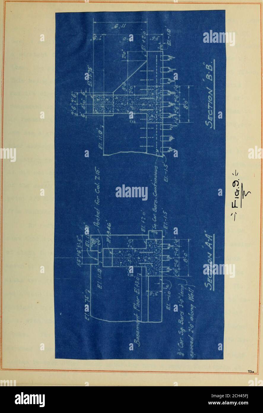
. The design of the Chicago and Northwestern Railway train shed . act any tension due to bending. The wall be- j ing 4 feet thick, according to the theory that the width of retain-ing walls should be 0,4 of the height, would be good as a retainingwall 10-0 high, whereas it is only 9-0, The 4«0 however, isdetermined by the column base. The only reinforcing, it v/ill beseen, is the vertical bars at the junction of wall and footing toresists shear and the longitudinal reinforcing just above the piles.These latter bars are to resist the tension in the footing, due toconsidering the footing as a be

Image details
Contributor:
Reading Room 2020 / Alamy Stock PhotoImage ID:
2CH45FJFile size:
7.1 MB (273.8 KB Compressed download)Releases:
Model - no | Property - noDo I need a release?Dimensions:
1306 x 1912 px | 22.1 x 32.4 cm | 8.7 x 12.7 inches | 150dpiMore information:
This image is a public domain image, which means either that copyright has expired in the image or the copyright holder has waived their copyright. Alamy charges you a fee for access to the high resolution copy of the image.
This image could have imperfections as it’s either historical or reportage.
. The design of the Chicago and Northwestern Railway train shed . act any tension due to bending. The wall be- j ing 4 feet thick, according to the theory that the width of retain-ing walls should be 0, 4 of the height, would be good as a retainingwall 10-0 high, whereas it is only 9-0, The 4«0 however, isdetermined by the column base. The only reinforcing, it v/ill beseen, is the vertical bars at the junction of wall and footing toresists shear and the longitudinal reinforcing just above the piles.These latter bars are to resist the tension in the footing, due toconsidering the footing as a beam transmitting the column loads tothe piles. For calculating the footing is taken as an overhang- ing beam, ending 1-2 way betv/een the 26-9 spaces, supported on twocolunns 12»-0 or 12*-6 c. c. and loaded by the piles. Allowanceis made for continuity by taking M = l/l2 wi^ , instead of i/b wl*^or 2/3 the moment figured as a single beam. The straight linetheory of reinforcing concrete is used entirely. Why couldnt piers have been built here as at other places. ^and the wall built in between? This would have saved the foot-ing reinforcement and a lighter reinforced v/all could he used. How-ever, it is desired to have as much of the room possible south ofbent 4 available for a basement, and as it is also desirable to havea straight faced wall, one free from pilasters and nooks made bythem, the piers would have to b e below the top of the basenent floor.This being at elevation of +3.0 and the piers 9 feet deep would : require digging to an elevation of -6, 0, whereas the present ar-rangement only recjiires digging to about elevation -l.O. When itis remembered that the deeper excavation is the more expensive, onecan see a great advantage in the wall as designed. Then too, thepier arrangement would require more concrete. It will be in- teresting to note the method used to find the earth pressure althoughit did not determine the design of the above wall. The amount of the earth press